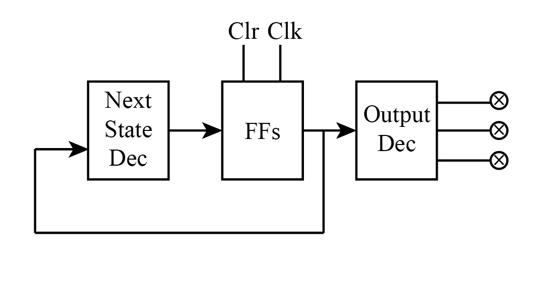
8) Design a binary counter that counts from 0 to 5. At each clock pulse, 3 lights will be ON and 3 lights will be OFF. Use JK flip flops. 国 Clr CIk Steps for solution: State diagram Next Output State FFs Dec Dec State table K-map reductions design
8) Design a binary counter that counts from 0 to 5. At each clock pulse, 3 lights will be ON and 3 lights will be OFF. Use JK flip flops. 国 Clr CIk Steps for solution: State diagram Next Output State FFs Dec Dec State table K-map reductions design

Chapter22: Sequence Control
Section: Chapter Questions
Problem 6SQ: Draw a symbol for a solid-state logic element AND.

Related questions
Question

Transcribed Image Text:8) Design a binary counter that counts from 0 to 5. At each clock pulse, 3 lights will be ON and 3 lights
will be OFF. Use JK flip flops.
国
Clr
CIk
Steps for solution:
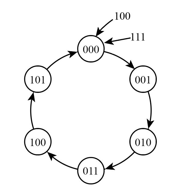
State diagram
Next
Output
State
FFs
Dec
Dec
State table
K-map reductions
design
Expert Solution
Step 1
Given data:
A binary counter that counts from 0 to 5
Step 2
Examination:
The binary counter is 0 to 5
State table using JK FLIP FLOP
| A | B | C | A+ | B+ | C+ | JA | KA | JB | KB | JC | KC |
| 0 | 0 | 0 | 1 | 0 | 0 | 1 | X | 0 | X | 0 | X |
| 1 | 0 | 0 | 0 | 1 | 0 | X | 1 | 1 | X | 0 | X |
| 0 | 1 | 0 | 1 | 1 | 0 | 1 | X | X | 0 | 0 | X |
| 1 | 1 | 0 | 0 | 0 | 1 | X | 1 | X | 1 | 1 | X |
| 0 | 0 | 1 | 1 | 0 | 1 | 1 | X | 0 | X | X | 0 |
| 1 | 0 | 1 | 0 | 0 | 0 | X | 1 | 0 | X | X | 1 |
| 0 | 1 | 1 | 0 | 0 | 0 | 0 | X | X | 1 | X | 1 |
| 1 | 1 | 1 | 0 | 0 | 0 | X | 1 | X | 1 | X | 1 |
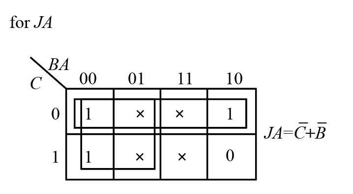
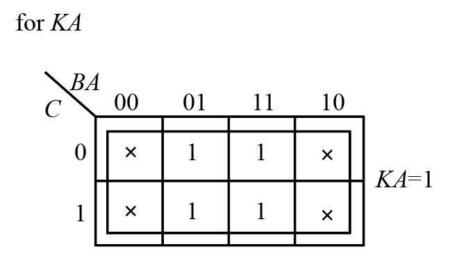
Step 3
K-map simplification

Step by step
Solved in 5 steps with 8 images

Knowledge Booster


Learn more about
Need a deep-dive on the concept behind this application? Look no further. Learn more about this topic, electrical-engineering and related others by exploring similar questions and additional content below.Recommended textbooks for you