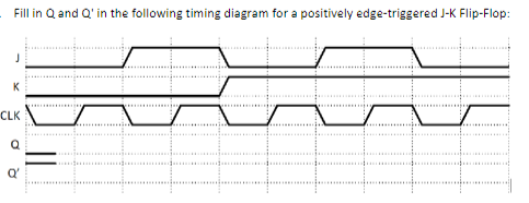
Fill in Q and Q' in the following timing diagram for a positively edge-triggered J-K Flip-Flop: K CLK Q


Q: The diagram below shows a view of an oscilloscope screen. The oscilloscope input is a sinusoidal…
A: Peak-to-peak voltage refers to the difference between the maximum positive and maximum negative…
Q: K-MAP THE FOLLOWING. SIMPLIFY THE LOGIC EQUATION FOR Z, IF POSSIBLE. THEN SIMPLIFY THE LOGIC…
A: Given Data:A truth table with,Inputs output To Find:The simplified logic expression for .The…
Q: Charge is uniformly distributed throughout a spherical volume of radius R with density pv. The…
A: We need to select correct option for electric field.
Q: 4. Negative value of second derivative of control function yields: a. Maximum solution of the…
A: As per the guidelines I am solving only first question.The question is from control systems subject.
Q: Determine the bus admittance matrix, Yous for the following system. Assume a three phase 100 MVA per…
A:
Q: Calculate the noise voltage output of a 1MΩ at 27°C over a 300kHz range
A: Given:Resistance, Temperature, Bandwidth, Need to calculate the noise voltage output for the given…
Q: Draw the Bode plot of the following systems and find their gain and phase margin. s + 100 (s+ 0.1)…
A: "Since you have posted a question with multiple questions, we will provide the solution only to the…
Q: ZT- Z₁ www R = 60 2₂ Z3 moo HE X = 10 Ω _ Xc = 12 Ω The angle of the total impedance is.......…
A: Given Data:An RLC series circuit with,Resistance Inductive reactance Capacitive reactance To Find:…
Q: An ideal transformer with turns ratio N1:N2 is used to connect a source to a load, as shown in Fig.…
A: The circuit is given ashere we need to calculate the turns ratio of transformer for maximum power…
Q: 1. Calculate the capacitor voltage vd) as a function of time. Include the voltage before the switch…
A: For the given RC circuit with DC excitation, we need to determine the capacitor voltage vC(t) and…
Q: Q1. A circuit is composed of two parallel branches, the first contains an impedance Z=202 + j4 , and…
A:
Q: When the frequency F= 5KHz, the effective bandwidth of the following signal is approximately…
A: Given:where f=5 KHz. we need to find:Effective bandwidth of the signal.
Q: Consider the circuit on the right, the resistors all have a resistance R. The equivalent resistance…
A: Given circuit,Value of resistances = RAsked to find the resistance seen by the voltage source?
Q: (a) With reference to the circuit configuration presented, describe in terms of voltages and…
A: Given circuit:Asked to find the,
Q: Vs 2mv Rs ww бока O V₁ Ri 100KS Ro 42 100V, 2 zio + Vo RL=452 For the following Voltage Gain…
A: The circuit diagram
Q: R1 www VCC VEE Vout(t) -O R2 Figure 1. Schematic for Problems B1-B4. 1. For the op amp circuit shown…
A: We need to find out gain and output voltage for given circuit.
Q: Q1: For each of the system below, determines the expression for the system frequency response (H…
A: Given Data:A discrete-time system is given in which the relationship between the input and output…
Q: Compare between Flip-flop and Latch in four points
A: Flip-flop - A flip-flop is a type of digital memory circuit that can hold one bit of data. They are…
Q: A O VAB в о 一个 11 www R1 ✓ 12 M R2 → 13 M R
A:
Q: A 240V, 60 Hz source is suppling power the following loads Load 1: 10KVA @ pf = 0.55 lagging Load 2:…
A:
Q: Find the equivalent inductance Leq at the terminals of the given circuit, where L = 6 mH. L 8 mH m a…
A: Given circuit is drawn below:To find:Lab=?
Q: What’s the best way to connect both an HC-SR04 ultrasonic sensor and an NRF24L01 module to one ESP32…
A: We must use distinct GPIO pins for each module in order to connect an ESP32 board to an HC-SR04…
Q: Duestion (3): Using mesh analysis, find the power of the 10 V power supply, shown in Fig. 2, and…
A: given
Q: Consider the following state machine: The state machine will perform an arithmetic function on two…
A: According to the question, the state machine will perform an arithmetic function on two 4-bit…
Q: V2 = 5V + R₁ = 30Ω R2 = 450 V₁=3V R3 = 54N + 1 Ux ↑i = ¼ A R4-8192
A:
Q: Q.2. Find the Thevenin equivalent of the circuit at below at terminals a-b. Notice that the current…
A: Given circuit,Asked to find the Thevenin equivalent seen by terminals a and b.
Q: 3 Inverting Amplifiers Consider the inverting amplifier shown below. (a). Calculate the currents…
A: Given circuit,Asked ti find the,Currents flowing through all the resistors,Power dissipated in all…
Q: Calculate a series RC value that will produce a V = 1.23 V output at f = 446 Hz when V = 25V at f =…
A:
Q: Alert dont submit AI generated answer. Question 4: Using JK flip-flops, design a sequential circuit…
A:
Q: The Y-connected load has a balanced impedance Zp=348 + j(33.7) and a source voltage Van 249 53° V…
A: From the given question:Zp=348+j33.7ΩVan=249∠530VRw=127Ωaksed to calculate IaA
Q: A 4-phase variable reluctance stepping motor is shown in the diagram below. The stator
A:
Q: 20 A 2-53.13° The active power = The reactive power = ↑ The apparent power = R = 3 Ω W + VR- W VAR…
A: Given circuit,Asked to find the,Active power P =?Reactive power Q =?Apparant power S =?Power factor…
Q: 2. Sketch the function r(t) and find its Fourier transform X(w). t/T, 0 0 is a constant). =
A:
Q: A manufacturing plant has a load of 3650 Kva at a lagging power factor of 0.6635. A 500 hp…
A: Load apparent power(s)=3650 kVAExisting Power factor(PF)= 0.6635Desired power factor(PF)=…
Q: Q2\ The one-line diagram of a simple power system is shown in figure below. All impedances are…
A:
Q: Q3. Find the Thevenin equivalent circuit external to RL from the network shown in Figure 3.1 below.…
A: The circuit is given aswe need to calculate the thevenin equivalent across ab terminal.
Q: HW4/A train is driven by a DC machine with independent electrical excitation. At a speed of 1500…
A: Given table,Asked to explain the,We are authorized to answer three sub-parts at a time, since you…
Q: Problem 2: Question Consider the circuit diagram below. Solve for the voltage at node b and the…
A: The given circuit isWe need to determine the voltage at node b and the current through R5 using node…
Q: FIND I (t)
A: For the given circuit the value of the current through the capacitor needs to be calculated and the…
Q: Please provide every step to find the transfer function of this RLC circuit
A: Given:a circuit, we need to find:the transfer function of the given RLC circuit.
Q: this root locus problem using manual calculations, please include the steps Please answer in…
A: In the given questions we need to plot the root locus.
Q: The switch in the circuit of (Figure 1) has been in position a for a long time. At t = 0, it moves…
A: The given circuit isWe need to determine the expression of voltage vo(t) for t≥0.The time is…
Q: a)Find the fourier transform of the signals. 2^n sin(pi*n /4) u[-n]
A: Since you have posted multiple questions, we will provide the solution only to the first question as…
Q: Consider the circuit diagram below. Es 12 kV R₁ -38 ΚΩ R₂ a) If the efficiency of the circuit is…
A: The circuit diagram,The efficiency,
Q: 30 V /= 10 A Pi 10 V P2 20 V 14 AP4 P3 4 A 12 V Ps 0.41
A:
Q: Consider the device shown in the following figure 1: pressure p(t) Solid frame Piezoresistive…
A: Since you have posted multiple questions, we will solve the first question for you. If you require…
Q: The switch in the following Fig. has been closed for a long time, and it opens at t = 0. Find i(t)…
A:
Q: Find the total average power, reactive power, complex and apparent power. ST= units +j ST= |ST|= P₁…
A: Load 1
Q: For the given figure, v. = 38/38°V. Find the average power absorber by the 100 resistor. 492 -j502…
A: The circuit diagram,
Q: Design the lowest order Butterworth lowpass filter with -1 dB at cut-off frequency 1kHz, an a…
A: According to the question, we need to design the lowest order Butterworth lowpass filter with -1 dB…
Needs Complete solution with 100 % accuracy.


Trending now
This is a popular solution!

Step by step
Solved in 3 steps with 2 images


- Use T flip flops to design a counter with the repeated binary sequence: 0,1,3,5,7. The circuit is to be designed by treating the unused states as don’t care conditions. Sketch the state diagram Derive the state table Implement the circuit.Design the following counter using negative edge triggered JK Flip-Flops.1.Asynchronous MOD11 Up counterThe signals below, CK and D are the clock and D inputs to two different components: a D latch and a D flip-flop. Complete the timing diagram below for the outputs from a D latch and D flip-flop, Qlatch and Qff, respectively. (Digital Circuit) ...
- Design a synchronous counter with T flip-flops that goes through the following binary repeated sequence: 0, 1, 3 Show that when binary states 10 are considered as don't care conditions, the counter may not operate properly. Find a way to correct the design. Is the solution correct or not??Flip-flops Give the disadvantages and advantages of Positive Edge Triggering vs Negative Edge Trigerring. Then, give an example of digital circuit and explain where a) Positive Edge is used and b) Negative edge is usedFor the circuit below X=1,B=1,Y=1,C=1. What will be the next state for the flip-flop?A. set B. reset C. complement D. No change E. none
- 5U. Complete the timing diagram shown below for a negative-edge-triggered SR flip-flop. Assume that the Sand R inputs always meet the setup and hold time requirements for the SR flip-flop.Hint: Use the SR flip-flop characteristic table.(c) (i)kindly demonstrate, the difference between the output waveform of theoutput Q of D flip-flop and the Q of clocked R S flip-flop. (ii) How will you modify an asynchronous R S flip-flop so that when both theinputs R and S are 1, the flip-flop is set?Draw the circuit, and show the truth table, for the clocked Master-Slave JK flip-flop
- Design a 3-bit counter with the following repeated sequence: 0,1,3,5,7. Use JK FLip Flops.4. Obtain the timing diagram for Qm and Qs of the Master-slave D flip-flop.Show how an asynchronous counter with J-K flip-flops can be implemented having a modulus of eleven with a straight binary sequence from 0000 through 1010 . Draw the diagram.(need only handwritten solution .otherwise downvote.)