Problem 3. Logic Diagram of a tiny ALU with DFF Accumulator This problem involves building a tiny ALU performing 4-bit addition and using two 74SL74 (4 DFF's) and a 4-bit adder. Provide an implementation to perform the following ALU addition operation. Add A,B - This operation adds register A and input B and stores the result in register A. Create a 4-bit register using 4 D FFs which acts as an accumulator. This accumulator is connected with an adder and is performing the following task. The initial value of the accumulator is 0 and every time a clock pulse is given, it adds the current value of the accumulator (let's call it A) and a given 4-bit input B. The B input is provided using 4 input switches. Thus, the accumulator stores the addition of multiple 4-bit values provided to the ALU. Draw the Logic Diagram of a tiny ALU with DFF Accumulator. Use logical symbols, not IC chips. A logical diagram should contain block notations (such as Full Adder, D Flip-Flop, Decoder, Multiplexer) and gate symbols (such as AND, OR, and NOT).
Problem 3. Logic Diagram of a tiny ALU with DFF Accumulator This problem involves building a tiny ALU performing 4-bit addition and using two 74SL74 (4 DFF's) and a 4-bit adder. Provide an implementation to perform the following ALU addition operation. Add A,B - This operation adds register A and input B and stores the result in register A. Create a 4-bit register using 4 D FFs which acts as an accumulator. This accumulator is connected with an adder and is performing the following task. The initial value of the accumulator is 0 and every time a clock pulse is given, it adds the current value of the accumulator (let's call it A) and a given 4-bit input B. The B input is provided using 4 input switches. Thus, the accumulator stores the addition of multiple 4-bit values provided to the ALU. Draw the Logic Diagram of a tiny ALU with DFF Accumulator. Use logical symbols, not IC chips. A logical diagram should contain block notations (such as Full Adder, D Flip-Flop, Decoder, Multiplexer) and gate symbols (such as AND, OR, and NOT).

Chapter22: Sequence Control
Section: Chapter Questions
Problem 6SQ: Draw a symbol for a solid-state logic element AND.

Related questions
Question
Alert dont submit AI generated answer.
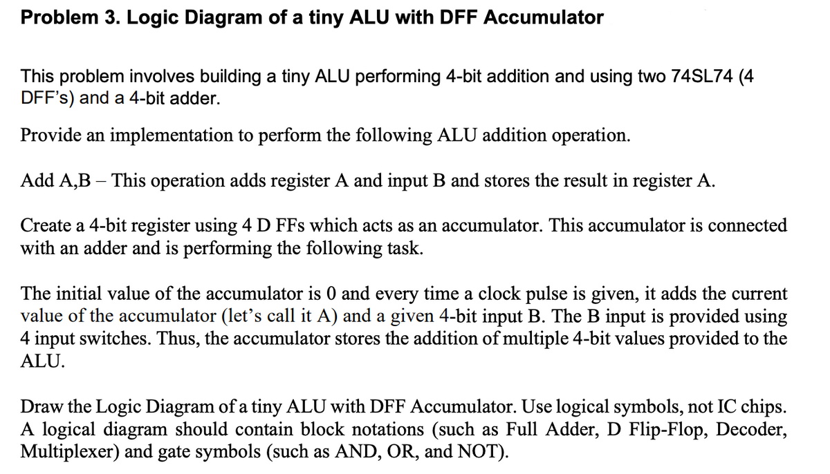
Transcribed Image Text:Problem 3. Logic Diagram of a tiny ALU with DFF Accumulator
This problem involves building a tiny ALU performing 4-bit addition and using two 74SL74 (4
DFF's) and a 4-bit adder.
Provide an implementation to perform the following ALU addition operation.
Add A,B - This operation adds register A and input B and stores the result in register A.
Create a 4-bit register using 4 D FFs which acts as an accumulator. This accumulator is connected
with an adder and is performing the following task.
The initial value of the accumulator is 0 and every time a clock pulse is given, it adds the current
value of the accumulator (let's call it A) and a given 4-bit input B. The B input is provided using
4 input switches. Thus, the accumulator stores the addition of multiple 4-bit values provided to the
ALU.
Draw the Logic Diagram of a tiny ALU with DFF Accumulator. Use logical symbols, not IC chips.
A logical diagram should contain block notations (such as Full Adder, D Flip-Flop, Decoder,
Multiplexer) and gate symbols (such as AND, OR, and NOT).
Expert Solution
This question has been solved!
Explore an expertly crafted, step-by-step solution for a thorough understanding of key concepts.

This is a popular solution!

Trending now
This is a popular solution!

Step by step
Solved in 3 steps with 2 images

Knowledge Booster


Learn more about
Need a deep-dive on the concept behind this application? Look no further. Learn more about this topic, electrical-engineering and related others by exploring similar questions and additional content below.Recommended textbooks for you