Veut Vin Vu 1kN 1kN c) c) Vin Veut Vin

Chapter59: Motor Startup And Troubleshooting Basics
Section: Chapter Questions
Problem 12SQ: How is a solid-state diode tested? Explain.

Related questions
Question

Transcribed Image Text:7)
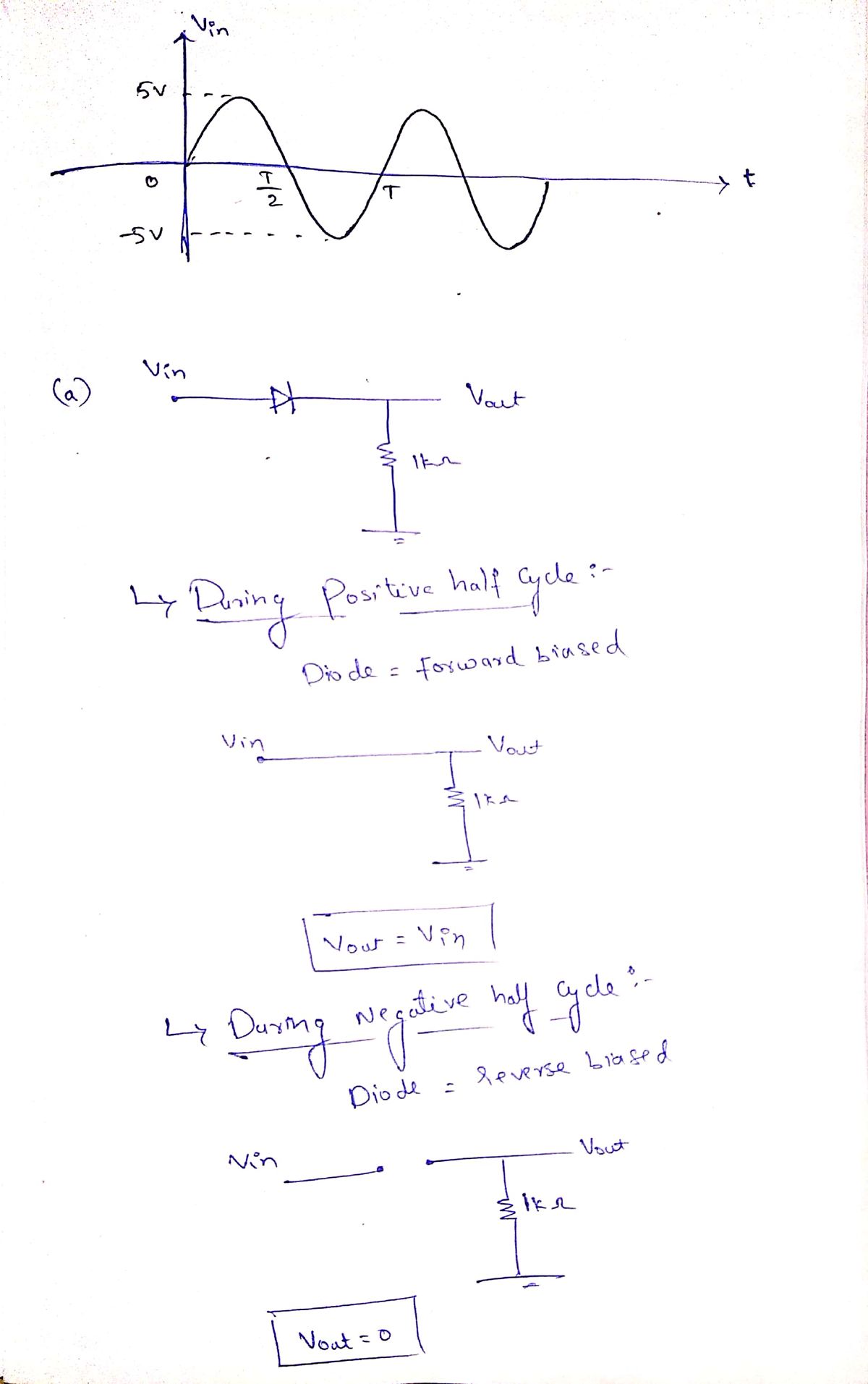
sine wave. Sketch the waveform (1 period is enough) for the resulting Vout- What are
its positive and negative peak values? (AVforward,ideal = 0)
For each of the ideal-diode circuits below, the input Vin is a 1kHz 5-V peak
a)
b)
Vin
Vaut
Vin
Vaut
1kN
1kN
c)
c)
Vin
Vout
Vin
Veut
1kN
1kN
e)
f)
Vin
1kN
Vaut
Vin
1kN
Vout
太太
Expert Solution
Step 1
*Multiple Sub- parts*
# as per our guidelines we are supposed to answer ?️only first 3️⃣ sub-parts. Kindly repost other parts as separate question
Thank you?
Step 2

Trending now
This is a popular solution!

Step by step
Solved in 4 steps with 3 images

Knowledge Booster


Learn more about
Need a deep-dive on the concept behind this application? Look no further. Learn more about this topic, electrical-engineering and related others by exploring similar questions and additional content below.Recommended textbooks for you