
Videos
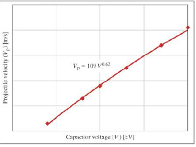
- 14. The data shown in the following graph was collected during testing of an electromagnetic mass driver. The energy to energize the electromagnets was obtained from a bank of capacitors. The capacitor bank was charged to various voltages, and for each voltage, the exit velocity of the projectile was measured when the mass driver was activated.
-
Note
Due to several complicated nonlinear losses in the system that are far beyond the
scope of this course, this is a case of a power model in which the exponent does not come out to be an integer or simple fraction, so rounding to two significant figures is appropriate. In fact, this model is only a first approximation-a really accurate model would be considerably more complicated.
-
- a. What would the velocity be if the capacitors were charged to 100,000 volts?
- b. What voltage would be necessary to accelerate the projectile to 1000 meters per second?
- c. Assume that the total capacitance is 5 farads. If the capacitors are initially charged to 10,000 volts and are discharged to 2000 volts during the launch of a projectile, what is the mass of the projectile if the overall conversion of energy stored in the capacitors to kinetic energy in the projectile has an efficiency of 20%? Recall that the energy stored in a capacitor is given by E = 0.5 CV2, where C is capacitance in farads and V is voltage in volts.

Trending nowThis is a popular solution!

Learn your wayIncludes step-by-step video

Chapter 12 Solutions
Thinking Like an Engineer: An Active Learning Approach (4th Edition)
Additional Engineering Textbook Solutions
Applied Fluid Mechanics (7th Edition)
Applied Statics and Strength of Materials (6th Edition)
INTERNATIONAL EDITION---Engineering Mechanics: Statics, 14th edition (SI unit)
Mechanics of Materials
Engineering Mechanics: Statics
Engineering Mechanics: Dynamics (14th Edition)


- You are the mechatronics engineer of a manufacturing plant. You decide to perform an analysis on a robot arm of the assembly line with the objective of optimizing its performance. After taking several readings of the speed of the arm’s end effector, you approximate its velocity to the function given below. v(t) = -t4 + 5t3 - 7t2 + 3t + 0.22 0 =< t =< 3 where the velocity is in ms-1 d) Knowing that the distance travelled by an object is the area under its velocity-time graph, determine the distance travelled by the end effector on the interval 0 =< t =< 1 by using the mid-ordinate rule. Simpson’s rule correct to 3 decimal places using four intervals. e) Calculate the same distance as in (d) above by using the appropriate definite integral. f) Compare the distances you calculated in (d) and (e) above and comment on the accuracy of the two methods you used in (d)arrow_forwardHarmonic oscillators. One of the simplest yet most important second-order, linear, constant- coefficient differential equations is the equation for a harmonic oscilator. This equation models the motion of a mass attached to a spring. The spring is attached to a vertical wall and the mass is allowed to slide along a horizontal track. We let z denote the displacement of the mass from its natural resting place (with x > 0 if the spring is stretched and x 0 is the damping constant, and k> 0 is the spring constant. Newton's law states that the force acting on the oscillator is equal to mass times acceleration. Therefore the differential equation for the damped harmonic oscillator is mx" + bx' + kr = 0. (1) k Lui Assume the mass m = 1. (a) Transform Equation (1) into a system of first-order equations. (b) For which values of k, b does this system have complex eigenvalues? Repeated eigenvalues? Real and distinct eigenvalues? (c) Find the general solution of this system in each case. (d)…arrow_forwardYou are the mechatronics engineer of a manufacturing plant. You decide to perform an analysis on a robot arm of the assembly line with the objective of optimizing its performance. After taking several readings of the speed of the arm’s end effector, you approximate its velocity to the function given below. v(t) = -t4 + 5t3 - 7t2 + 3t + 0.22 0 =< t =< 3 where the velocity is in ms-1 Use your knowledge of differentiation to sketch the velocity-time graph, clearly marking the critical points. Using the graph sketched in (a) above, estimate the velocity when t = 1.5 s Calculate the velocity of the function when t = 1.5 s by substituting to the velocity function. Compare this value to the value you estimated in b above.arrow_forward
- A chamber of unknown volume is filled with an unknown amount of ideal gas. A cylinder with an open bottom and calibrated volume is connected to the chamber and is closed with a movable piston. A gas pressure sensor is also mounted on the chamber as shown in the figure. The whole experimental setup is kept at a constant temperature of 300 K. Doris moves the piston from mark 0 to mark 200 mL in steps of 50 mL and records the corresponding pressure in the chamber (see the table below). She moves the piston very slowly and waits several minutes before recording the pressure values. VCyl(mL) P(105N/m2)) 0 4.35 50 3.85 100 3.50 150 3.15 200 2.90 Determine the volume of the chamber using Doris's data in the table. (Note: This is a problem that requires linearization of data.) Determine the number of moles of gas. (Note: This is a problem that requires linearization of data.)arrow_forwardSuppose that the total cost function for an is linear, that the marginal cost is $54, and that the total cost for 50 players is $8700. Write the equation of this MP3 player cost function and then graph it.arrow_forwardLearning Goal: To use the principle of linear impulse and momentum to relate a force on an object to the resulting velocity of the object at different times. The equation of motion for a particle of mass m can be written as ∑F=ma=mdvdt By rearranging the terms and integrating, this equation becomes the principle of linear impulse and momentum: ∑∫t2t1Fdt=m∫v2v1dv=mv2−mv1 For problem-solving purposes, this principle is often rewritten as mv1+∑∫t2t1Fdt=mv2 The integral ∫Fdt is called the linear impulse, I, and the vector mv is called the particle's linear momentum. A tennis racket hits a tennis ball with a force of F=at−bt2, where a = 1300 N/ms , b = 300 N/ms2 , and t is the time (in milliseconds). The ball is in contact with the racket for 2.90 ms . If the tennis ball has a mass of 59.7 g , what is the resulting velocity of the ball, v, after the ball is hit by the racket?arrow_forward
- A control valve is used to manipulate a liquid flowrate in the flowrate control loop. Figure 2 shows the flow characteristic of the control valve.Determine the following: i. Type of flow characteristic of the control valve.ii. Flowrate through the valve if the valve travel is 45%. Noted that the flowrate of the liquid is 70 000 lb/h when the valve is fully opened.iii. The maximum flow coefficient of the control valve, if the density of the liquid is half of the density of water and the pressure drop across the valve is 10 psi.arrow_forward3. Properties of Pump Systems - II Learning Objectives: This problem builds on the pump examples we have been doing, but is meant to help you learn to do proofs in a step by step fashion. Can you generalize intuition from a simple example? We consider a system of reservoirs connected to each other through pumps. An example system is shown below in Figure 1, represented as a graph. Each node in the graph is marked with a letter and represents a reservoir. Each edge in the graph represents a pump which moves a fraction of the water from one reservoir to the next at every time step. The fraction of water moved is written on top of the edge. Figure 1: Pump system We want to prove the following theorem. We will do this step by step. Theorem: Consider a system consisting of k reservoirs such that the entries of each column in the system's state transition matrix sum to one. If s is the total amount of water in the system at timestep n, then total amount of water at timestep n +1 will also be…arrow_forwardThe complete slide- back and forth motion of a single reciprocating compressor piston completes in a 2-sec period. The volume displacement of the piston though the piston cylinder is 8,902.63 in3. The stiffness of crank is said to be equal to 65.5N/m and the mass of the said piston is at 10kgs. Obtain the following 1. Plot the graph of the following relationship: A) Position vs Time graph B) Velocity vs Time C) Acceleration vs Timearrow_forward
- 5.Design a system to measure the bending moment (up and down) and torque in the tail boom of the human-powered aircraft shown below. You will need two Wheatstone bridges. Your system should measure the bending and torque independently, but not be sensitive to any other internal forces, like axial force, transverse shear, or bending moment about the vertical axis (back and forth). (If relevant) A clearly labeled diagram (or diagrams) about your analysis with a coordinate system and relevant labels. Final answer with appropriate units and significant figures. You can use the fprintf() command in MATLAB to format numerical results A 2-3 sentence reflection on your answer. Does it make sense? Why or why not? What are some implications? (a) Make a few clear, labeled sketches showing approximately where you would place the strain gauges. Consider the location (along the length of the boom), positioning (around the circumference of the boom), and orientation of the gauges. Show clearly…arrow_forwardLearning Goal: To calculate minor head losses and pressure drops for pipe fittings. Minor losses in pipe flow are the result of disruptions to the steady laminar or turblent flow in a pipe by entrances, bends, transitions, valves or other fittings. In general, calculating these losses analytically is too complex. However, all of these losses can be modeled using terms of the form h = KL where Kr, is called the loss coefficient and is determined experimentally. This coefficient relates the minor head loss to the velocity head for the flow. For expansions and contractions, the loss coefficient is calculated using nine the velocity for the smaller diameter pipe. The table below gives some representative values for various minor head losses. These are representative only, and a more complete table would account for different kinds of fittings and connections (like threaded or soldered). Fitting Well-rounded entrance ≥0.15 Flush entrance Re-entrant pipe Discharge pipe Sudden contraction (d₂…arrow_forwardTwo tanks are connected in the following unusual manner. F₁ Notes: h₂ F₂ J h₂ What are the algebraic equations & ODEs that can be used to find h₁, h₂, F₂, & F3 as functions of time for any given variations in inputs. b. Identify all input & output variables. The density of the incoming liquid, p, is constant. The cross-sectional areas of the two tanks are A and Ą. F₂ is positive for flow from Tank 1 to Tank 2. The two valves are linear with valve coefficients C₂ and C3. Both tanks are open to the atmosphere.arrow_forward
 Elements Of ElectromagneticsMechanical EngineeringISBN:9780190698614Author:Sadiku, Matthew N. O.Publisher:Oxford University Press
 Mechanics of Materials (10th Edition)Mechanical EngineeringISBN:9780134319650Author:Russell C. HibbelerPublisher:PEARSON
 Thermodynamics: An Engineering ApproachMechanical EngineeringISBN:9781259822674Author:Yunus A. Cengel Dr., Michael A. BolesPublisher:McGraw-Hill Education
 Control Systems EngineeringMechanical EngineeringISBN:9781118170519Author:Norman S. NisePublisher:WILEY
 Mechanics of Materials (MindTap Course List)Mechanical EngineeringISBN:9781337093347Author:Barry J. Goodno, James M. GerePublisher:Cengage Learning
 Engineering Mechanics: StaticsMechanical EngineeringISBN:9781118807330Author:James L. Meriam, L. G. Kraige, J. N. BoltonPublisher:WILEY