
Statics and Mechanics of Materials (5th Edition)
5th Edition
ISBN: 9780134382593
Author: Russell C. Hibbeler
Publisher: PEARSON
expand_more
expand_more
format_list_bulleted
Concept explainers
Videos
Textbook Question
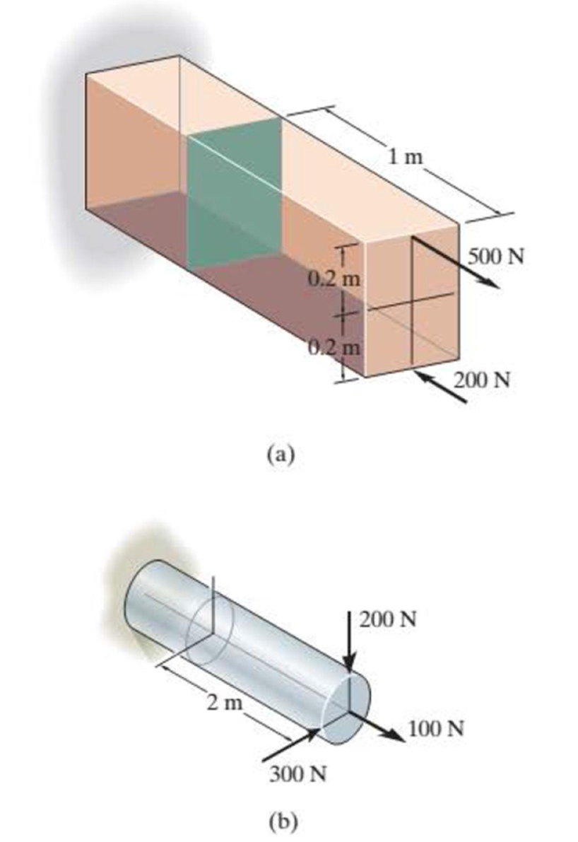
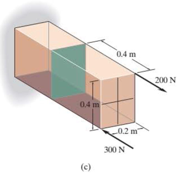
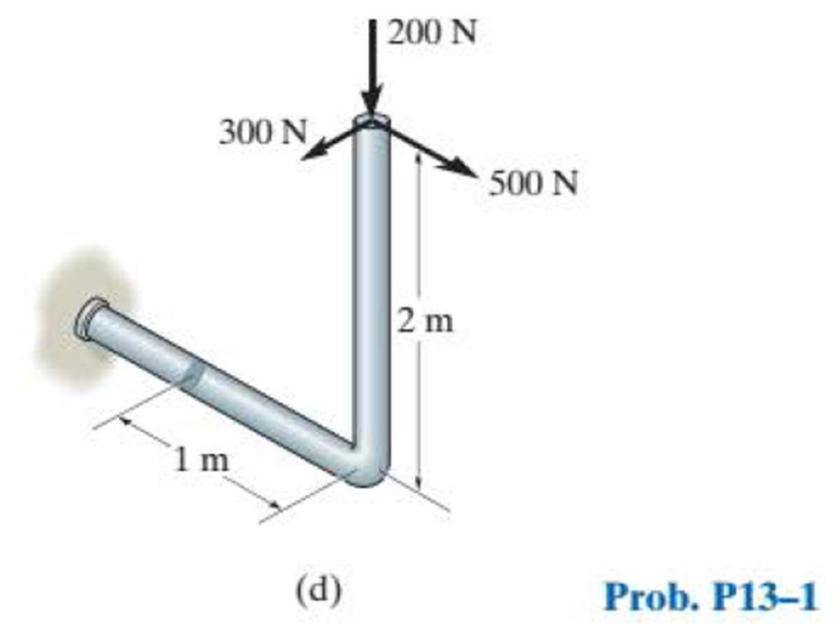
Chapter 13.2, Problem 1PP
In each case, determine the internal loadings that act on the indicated section. Show the results on the left segment.
Expert Solution & Answer
Want to see the full answer?
Check out a sample textbook solution
Students have asked these similar questions
Determine the resultant internal loadings acting on the cross section at B of the pipe shown. End A is subjected to a vertical force P and a horizontal force Q. Use P = 90 N and Q = 70 N.
a. Determine the internal axial force (in N) in section B.
b. Determine the internal shear force (in N) in section B.
c. Determine the internal torque (in N-m) in section B.
With FBD please thank you.
Use Mohr’s circle to determine the normal stress and shear stress acting on the inclined plane AB.
If the allowable normal stress is 120MPa and the allowable shear stress is 60MPa, what is the resultant force at the support A?
Chapter 13 Solutions
Statics and Mechanics of Materials (5th Edition)
Ch. 13.1 - A spherical gas tank has an inner radius of r =...Ch. 13.1 - A pressurized spherical tank is made of...Ch. 13.1 - The thin-walled cylinder can be supported in one...Ch. 13.1 - Prob. 4PCh. 13.1 - Prob. 5PCh. 13.1 - Determine the maximum force P that can be exerted...Ch. 13.1 - Prob. 7PCh. 13.1 - The steel water pipe has an inner diameter of 12...Ch. 13.1 - The steel water pipe has an inner diameter of 12...Ch. 13.1 - The A-36-steel band is 2 in. wide and is secured...
Ch. 13.1 - The gas pipe line is supported every 20 ft by...Ch. 13.1 - Prob. 12PCh. 13.1 - An A-36-steel hoop has an inner diameter of 23.99...Ch. 13.1 - The ring, having the dimensions shown, is placed...Ch. 13.1 - Prob. 15PCh. 13.1 - Prob. 16PCh. 13.1 - Prob. 17PCh. 13.2 - In each case, determine the internal loadings that...Ch. 13.2 - The internal loadings act on the section. Show the...Ch. 13.2 - Determine the normal stress at comers A and B of...Ch. 13.2 - Determine the state of stress at point A on the...Ch. 13.2 - Determine the state of stress at point A on the...Ch. 13.2 - Determine the magnitude of the load P that will...Ch. 13.2 - Prob. 5FPCh. 13.2 - Determine the state of stress at point A on the...Ch. 13.2 - Determine the state of stress at point A on the...Ch. 13.2 - Determine the state of stress at point A on the...Ch. 13.2 - Determine the shortest distance d to the edge of...Ch. 13.2 - Determine the maximum distance d to the edge of...Ch. 13.2 - The plate has a thickness of 20 mm and the force P...Ch. 13.2 - If the load has a weight of 600 lb, determine the...Ch. 13.2 - The steel bracket is used to connect the ends of...Ch. 13.2 - Prob. 23PCh. 13.2 - The column is built up by gluing the two boards...Ch. 13.2 - Prob. 25PCh. 13.2 - The screw of the clamp exerts a compressive force...Ch. 13.2 - Prob. 27PCh. 13.2 - Prob. 28PCh. 13.2 - The joint is subjected to the force system shown....Ch. 13.2 - Prob. 30PCh. 13.2 - The 12-in.-diameter holt hook is subjected to the...Ch. 13.2 - Prob. 32PCh. 13.2 - Prob. 33PCh. 13.2 - Prob. 34PCh. 13.2 - Prob. 35PCh. 13.2 - The drill is jammed in the wall and is subjected...Ch. 13.2 - The drill is jammed in the wall and is subjected...Ch. 13.2 - The frame supports the distributed load shown....Ch. 13.2 - Prob. 39PCh. 13.2 - The rod has a diameter of 40 mm. If it is...Ch. 13.2 - The rod has a diameter of 40 mm. If it is...Ch. 13.2 - The beveled gear is subjected to the loads shown....Ch. 13.2 - The beveled gear is subjected to the loads shown....Ch. 13.2 - Determine the normal-stress developed at points A...Ch. 13.2 - Sketch the normal-stress distribution acting over...Ch. 13.2 - Prob. 46PCh. 13.2 - The solid rod is subjected to the loading shown....Ch. 13.2 - Prob. 48PCh. 13.2 - Prob. 49PCh. 13.2 - The C-frame is used in a riveting machine. If the...Ch. 13.2 - Prob. 51PCh. 13.2 - The uniform sign has a weight of 1500 lb and is...Ch. 13.2 - The uniform sign has a weight of 1500 lb and is...Ch. 13 - The post has a circular cross section of radius c....Ch. 13 - The 20-kg drum is suspended from the hook mounted...Ch. 13 - The 20-kg drum is suspended from the hook mounted...Ch. 13 - Prob. 4RPCh. 13 - If the cross section of the femur at section aa...Ch. 13 - Prob. 6RPCh. 13 - Prob. 7RPCh. 13 - Prob. 8RP
Knowledge Booster


Learn more about
Need a deep-dive on the concept behind this application? Look no further. Learn more about this topic, mechanical-engineering and related others by exploring similar questions and additional content below.Similar questions
- Use Mohr's Circle to determine the maximum shear stress on the element, also using Mohr's Circle determine the maximum normal stress on the element.arrow_forwardDetermine the resultant internal loadings acting at the circular cross- section passing by points A and B as shown in the figure below. The correct answers should be given according to the positive sign convention. y 0.51 Barrow_forwardDetermine the ff: •Internal bending moment at point c •internal shear force at point c •internal normal force at point c Asap please.arrow_forward
- 5/5 find the normal stress at left of point C A 100 C 40 kN 50 kN 40 mm 70 10 kN 20 mm 30 mm 100 mm 300 mm 300 mm 200mm B.arrow_forwardIn each case, the state of stress sx, sy, txy produces normal and shear stress components along section AB of the element that have values of sx = -5 kPa and tx y = 8 kPa when calculated using the stress transformation equations.Establish the x and y axes for each segment and specify the angle u, then show these results acting on each segment.arrow_forwardDetermine the combined loadings and draw them on a volume element: (a)Section A-A, Point A on the cross section (b)Section B-B, Point B on the cross sectionarrow_forward
- A moment about the z-axis of 192 N-m is applied to a beam with dimensions b = 85 mm and h = 302 mm. If there are no other loads applied to the beam (My, P, Vy and Vz = 0), what is the normal stress at point F? Give your answer in kPa to two decimal places with negative indicating compression and positive indicating tension. b/4 М, h E Ihis F h/3 В M. D b/4arrow_forwardThe hook is subjected to the force of 80 lb. Determine the state of stress at point B at section a–a. The cross section has a diameter of 0.5 in. Use the curved-beam formula to calculate the bending stress.arrow_forwardUsing the same figure, determine the components of force F along X-Y axes which are parallel and perpendicular to the incline. F = 260lbs 12 F, = Fr Y 5 P = 361lbs 12 3 4arrow_forward
- What steps should be taken to obtain The resultant internal loadings at a point located on the section of a body using the method of sections?arrow_forwardTwo fully loaded tractor trailers travel over the bridge putting substantial loading on the structure. As they pass over the middle of the bridge, one of the vertical supporting pillars, which is fixed at its bottom, deforms as shown below. The weight of the trucks causes point T to move to point T'—a distance of 2.5 cm along the x-axis. If the pillar has an original height of 27 m , find the shear strain at point T.arrow_forwardA stress element in a rock mass making up a slope experiences a 2D stress as follows: σx = 8 MPa, σy = 4 MPa , tauxy = 3 MPa A. By using the stress transformation equation, draw a curve of the stress variation experienced by the stress element at the axis of rotation angle θ = 0-180°. Use the interval θ = 1°, with the x-axis and stress as the y-axis. Mark on the curve where the principal stress and maximum shear stress occur. Draw the three stress curves completely and neatly B. Draw the stress element along with the magnitude and direction of the stress at the angle where the principal stress occurs and at the angle where the maximum shear stress occurs. C. Write down the direction vectors of the orientation of the principal stress (n1, and n₂) and the maximum shear stress (nmax). Write it in unit vector form i and j. D. Prove that the value of the stress invariant (I1, and I2) using the principal stress is reached and prove that the orthogonality condition of the direction cosine is…arrow_forward
arrow_back_ios
SEE MORE QUESTIONS
arrow_forward_ios
Recommended textbooks for you
 Elements Of ElectromagneticsMechanical EngineeringISBN:9780190698614Author:Sadiku, Matthew N. O.Publisher:Oxford University Press
 Mechanics of Materials (10th Edition)Mechanical EngineeringISBN:9780134319650Author:Russell C. HibbelerPublisher:PEARSON
 Thermodynamics: An Engineering ApproachMechanical EngineeringISBN:9781259822674Author:Yunus A. Cengel Dr., Michael A. BolesPublisher:McGraw-Hill Education
 Control Systems EngineeringMechanical EngineeringISBN:9781118170519Author:Norman S. NisePublisher:WILEY
 Mechanics of Materials (MindTap Course List)Mechanical EngineeringISBN:9781337093347Author:Barry J. Goodno, James M. GerePublisher:Cengage Learning
 Engineering Mechanics: StaticsMechanical EngineeringISBN:9781118807330Author:James L. Meriam, L. G. Kraige, J. N. BoltonPublisher:WILEY
Elements Of Electromagnetics
Mechanical Engineering
ISBN:9780190698614
Author:Sadiku, Matthew N. O.
Publisher:Oxford University Press
Mechanics of Materials (10th Edition)
Mechanical Engineering
ISBN:9780134319650
Author:Russell C. Hibbeler
Publisher:PEARSON
Thermodynamics: An Engineering Approach
Mechanical Engineering
ISBN:9781259822674
Author:Yunus A. Cengel Dr., Michael A. Boles
Publisher:McGraw-Hill Education
Control Systems Engineering
Mechanical Engineering
ISBN:9781118170519
Author:Norman S. Nise
Publisher:WILEY
Mechanics of Materials (MindTap Course List)
Mechanical Engineering
ISBN:9781337093347
Author:Barry J. Goodno, James M. Gere
Publisher:Cengage Learning
Engineering Mechanics: Statics
Mechanical Engineering
ISBN:9781118807330
Author:James L. Meriam, L. G. Kraige, J. N. Bolton
Publisher:WILEY
Types Of loads - Engineering Mechanics | Abhishek Explained; Author: Prime Course;https://www.youtube.com/watch?v=4JVoL9wb5yM;License: Standard YouTube License, CC-BY