Draw the influence lines for (a) the moment at C, (b) the vertical reaction at A, and (c) the shear at C. Assume A is a fixed support. Solve this problem using the basic method of Sec. 6.1.
(a)
The influence lines for the moment at
Answer to Problem 6.1P
The influence line for the moment at
Explanation of Solution
Concept Used:
The unit load as
Calculation:
The following figure shows the free body diagram of the beam.
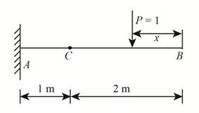
Figure-(1)
Write the equilibrium equation for the moment about point
Here, the net moment about the point
When the point load is at
Substitute,
When the point load is at
Substitute,
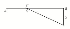
Conclusion:
According to the value of

Figure-(2)
(b)
The influence line for the vertical reaction at
Answer to Problem 6.1P
The influence line for the vertical reaction at
Explanation of Solution
Concept Used:
The unit load as
Calculation:
The following figure shows the free body diagram of the beam.
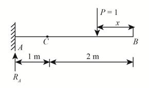
Figure-(3)
Write the equilibrium equation for the forces acting in the vertical direction.
Here, summation of the vertical forces is
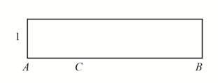
Conclusion:
According to the value of the vertical reaction at

Figure-(4)
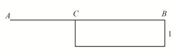
(c)
The influence line for the shear at
Answer to Problem 6.1P
The influence line for the shear at
Explanation of Solution
Concept Used:
The unit load as
Calculation:
Consider the right segment of the beam as shown in Figure-(5).
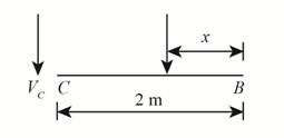
Figure-(5)
Write the equilibrium equation for the forces acting in the vertical direction.
Here, summation of the vertical forces is
Now, consider the left segment of the beam as shown in Figure-(6).
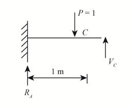
Figure-(6)
Write the equilibrium equation for the forces acting in the vertical direction.
Conclusion:
According to the values of

Figure-(7)
Want to see more full solutions like this?
Chapter 6 Solutions
Structural Analysis (10th Edition)
Additional Engineering Textbook Solutions
Foundation Design: Principles and Practices (3rd Edition)
Elementary Surveying: An Introduction To Geomatics (15th Edition)
Materials for Civil and Construction Engineers (4th Edition)
Elementary Surveying (14th Edition)
Starting Out With Visual Basic (7th Edition)
Manufacturing Engineering & Technology

- Assume that the loads are being transmitted to the bottom of the truss in the diagram below. For members DI and EK, make a chord and create the influence lines. Also, take into account the three-point moving load. a= 5.4 (m) b= 7.3 (m) c= 70 (kN) d= 90 (kN) Determine the following member forces as displayed. Assume the loads are only moving to the right. a. Maximum tension on member DI in kN; if none, enter "0." b. Maximum compression on member DI in kN; if none, enter "0." c. Maximum tension on member EK in kN; if none, enter "0." d. Maximum compression on member EK in kN; if none, enter "0."arrow_forwardAssume that the loads are being transmitted to the bottom of the truss in the diagram below. For members DI and EK, make a chord and create the influence lines. Also, take into account the three-point moving load. Determine the following member forces as displayed. Assume the loads are only moving to the right. a. Maximum tension on member DI in kN; if none, enter "0." b. Maximum compression on member DI in kN; if none, enter "0." c. Maximum tension on member EK in kN; if none, enter "0." d. Maximum compression on member EK in kN; if none, enter "0." Take note that a = 5.1 m b = 6.3 m c = 62 kN d = 78 kN Is the given valuesarrow_forwardAssume that the loads are being transmitted to the bottom of the truss in the diagram below. For members DI and EK, make a chord and create the influence lines. Also, take into account the three-point moving load. Determine the following member forces as displayed. Assume the loads are only moving to the right. a. Maximum tension on member DI in kN; if none, enter "0." b. Maximum compression on member DI in kN; if none, enter "0." c. Maximum tension on member EK in kN; if none, enter "0." d. Maximum compression on member EK in kN; if none, enter "0." Take note that a = 4.2m, b = 5.3m, c = 52kN, d = 69kN Is the given values.arrow_forward
- Please show complete solution. Draw the influence line for: a) The vertical reaction at B, b) The shear at A, c) The moment at Carrow_forwardSketch the influence lines for the vertical reaction at A, the shear at B, and the moment at Barrow_forwardDraw the influence line diagram for the force in member BF of the truss to answer the questions below. All members have the same length. G F E 60° 60° D B. -20 ft- 20 ft- -20 ft- What is the [ Choose v ordinate when x = 20 ft? What is the [ Choose v ordinate when x = 40 ft?arrow_forward
- Draw the influence line for the shear at C. Plot numerical values every 1.5 m. Assume A is fixed and the support at B is a roller. EI is constant.arrow_forwarda.)Draw the influence lines for the vertical reaction at A, the shear at C, and the moment at C. Solve this problem using the basic method. b.)Draw the influence lines for the vertical reaction at A, the shear at C, and the moment at C. Solve this problem using the Muller-Breslau principle.arrow_forwardDraw the influence lines for members DK and CI assuming that the loads in the illustrated truss are being transmitted to the bottom chord. Considering the provided 3 - point moving load, calculate the following member forces. Assume that the loads only move to the right. Questions a. Maximum tension on member DK in kN. b. Maximum compression on member DK in kN. c. Maximum tension on member CI in kN. d. Maximum compression on member CI in kN. Please answer correctly and show neat solutions. thank you. Plz don't reject. I'll rate.arrow_forward
- Assume that the loads are being transmitted to the bottom chord in the truss depicted, and draw the influence lines for members DK and CI. Determine the following member forces using the 3 point moving load indicated. Assume the loads only move to the right. Questions a. Maximum tension on member DK in kN. b. Maximum compression on member DK in kN. c. Maximum tension on member CI in kN. d. Maximum compression on member CI in kN.arrow_forward2. a. Draw the influence line for member BF of the truss shown. The bottom chord is the loaded chord. b. At what Joint on the truss will a concentrated live load be placed to produce a maximum tensile force in the member BF?arrow_forward1.3-3 Segments AB and BC of beam ABC are pin connected a small distance to the right of joint B (see figure). Axial loads act at A and at the mid-span of AB. A concentrated moment is applied at joint B. (a) Find reactions at supports A, B, and C. (b) Find internal stress resultants N, V, and M at 4.5 m. 136 N-m at joint B 3m 440 N A 220 N В C 6 m 3 m Pin connection PROBLEM 1.3-3arrow_forward

 Structural Analysis (10th Edition)Civil EngineeringISBN:9780134610672Author:Russell C. HibbelerPublisher:PEARSON
 Principles of Foundation Engineering (MindTap Cou...Civil EngineeringISBN:9781337705028Author:Braja M. Das, Nagaratnam SivakuganPublisher:Cengage Learning
 Fundamentals of Structural AnalysisCivil EngineeringISBN:9780073398006Author:Kenneth M. Leet Emeritus, Chia-Ming Uang, Joel LanningPublisher:McGraw-Hill Education
 Traffic and Highway EngineeringCivil EngineeringISBN:9781305156241Author:Garber, Nicholas J.Publisher:Cengage Learning