
Videos
The beam AB is pin supported at A and supported by a cable BC. A separate cable CG is used to hold up the frame. If AB weighs 120 lb/ft and the column FC has a weight of 180 lb/ft, determine the resultant internal loadings acting on cross sections located at points D and E. Neglect the thickness of both the beam and column in the calculation.
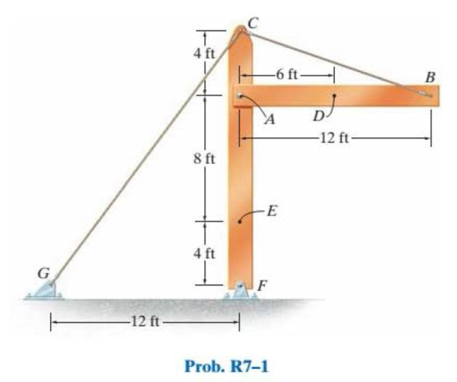
Find the resultant internal loadings acting on cross sections located at D and E.
Answer to Problem 1RP
The resultant internal loadings at cross section at D are
The resultant internal loadings at cross section at E are
Explanation of Solution
Given information:
The beam AB is pin supported at A and supported by a cable BC.
The weight of the beam AB is
The weight of the column FC is
Calculation:
Find the loading at the center of the beam AB
Substitute
Convert the unit from lb to kip.
Sketch the Free Body Diagram of the beam AB shown in Figure 1.
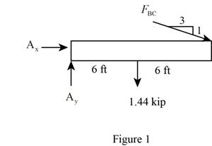
Refer to Figure 1.
Find the angle of cable BC to the horizontal
Find the tension in cable BC as shown below.
Take moment about A is Equal to zero.
Find the support reaction at A as shown below.
Apply the Equations of Equilibrium as shown below.
Summation of forces along horizontal direction is Equal to zero.
Summation of forces along vertical direction is Equal to zero.
Find the loading at the center of the beam AD
Substitute
Convert the unit from lb to kip.
Sketch the Free Body Diagram of the section for point D as shown in Figure 2.
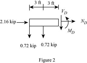
Refer to Figure 2.
Find the internal loadings as shown below.
Apply the Equations of Equilibrium as shown below.
Summation of forces along horizontal direction is Equal to zero.
Summation of forces along vertical direction is Equal to zero.
Take moment about D is Equal to zero.
Hence, the resultant internal loadings at cross section at D are
Find the loading at the center of the column FC
Substitute
Convert the unit from lb to kip.
Sketch the Free Body Diagram of the beam FC shown in Figure 3.
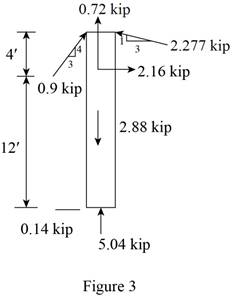
Refer to Figure 3.
Find the angle of cable CG to the horizontal.
Find the tension in cable CG as shown below.
Summation of forces along horizontal direction is Equal to zero.
Find the loading at the center of the column FE
Substitute
Convert the unit from lb to kip.
Sketch the Free Body Diagram of the section for point E as shown in Figure 4.
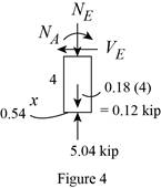
Refer to Figure 4.
Find the internal loadings as shown below.
Apply the Equations of Equilibrium as shown below.
Summation of forces along horizontal direction is Equal to zero.
Summation of forces along vertical direction is Equal to zero.
Take moment about E is Equal to zero.
Therefore, the resultant internal loadings at cross section at E are
Want to see more full solutions like this?
Chapter 7 Solutions
Statics and Mechanics of Materials (5th Edition)
Additional Engineering Textbook Solutions
Manufacturing Engineering & Technology
Foundations of Materials Science and Engineering
HEAT+MASS TRANSFER:FUND.+APPL.
Engineering Mechanics: Dynamics (14th Edition)
DeGarmo's Materials and Processes in Manufacturing
Shigley's Mechanical Engineering Design (McGraw-Hill Series in Mechanical Engineering)


- A 200-lb man starts at end A of the wooden plank and walks toward end B. If the plank will fail when the maximum bending stress is 6000 psi, find the farthest distance x that the man can walk safely.arrow_forwardThe 460-kg uniform beam is subjected to the three external loads shown. Compute the reactions at the support point O. The x-y plane is vertical. Positive values are to the right, up, and counterclockwise. 0 1.2 m Answers: Ox Oy = i Mo= i i A 6.1 KN 1.6 m 19 kN.m B kN kN 1.6 m kN-m 20 C 2.7 KN -1xarrow_forwardDetermine the magnitude of the vertical force C, for the simply supported beam, where w = 11 kips/ft, L1 = 9 ft and L2 = 5 ft.arrow_forward
- The vertical load on the hook is 1000 lb. Draw the appropriate free-body diagrams and determine the maximum average shear force on the pins at A, B, and C. Note that due to symmetry four wheels are used to support the loading on the railing.arrow_forwardThe beam shown has an overall length L of 6.9 metres. A uniform distributed load of 3.9 kN/m is applied as shown. If the distance x is 1.9 metres, determine the magnitude (in kNm) of the reaction moment at A. Note: Do NOT include the units in your answer.arrow_forward2-13.10. A beam of length L supports a load which varies uniformly from w lb/ft at the right end to zero at the left end. Show that the resultant load is W = wL/2 acting at L/3 from the right end.arrow_forward
- The beam supports the triangular distributed load shown. Determine the resultant internal loadings on the cross section at point C. Assume the reactions at the supports A and B are vertical.arrow_forward5. The cable supports the three loads shown. Determine the magnitude of P1 if P2 = 600 N and yn = 3 m. Also find sag yp 1 m |E Ув YD 4 m B D C P2 P, P - 3 m - 6 m 6 m - - 3 marrow_forwardYour answer is partially correct. The 410-kg uniform beam is subjected to the three external loads shown. Compute the reactions at the support point O. The x-y plane is vertical. Positive values are to the right, up, and counterclockwise. y 37 3.0 kN 39 kN m A B 5.8 kN -1.2 m- 1.8 m 1.8 m Answers: O, = 1.805 kN O, = 0.614 kN Mo = i 22173.54 kN-m eTextbook and Media Attempts: unlimited Submit Answer Save for Laterarrow_forward
- 4. Determine the force at roller B if a 15 mm gap resulted from a construction error. Compare the maximum moment in the beam to the case if no gap existed. The steel beam is a W250x32.7 16 kN/m B 15 mm 4 m 6 marrow_forward5. The cable supports the three loads shown. Determine the magnitude of Pi if P2 = 600 N and yB = 3 m. Also find sag yn E 1 m A Ув yD 4 m B D P2 P2 P, 6 m- - 3 m- 6 m - 3 marrow_forwardThe compound beam is supported by a roller at point C, fixed at point A, and the two sections are pinned at point B. It is subjected to a free couple moment M, a distributed load with maximum load intensity w, and a concentrated force F. If the distributed load w = 0.6 kN/m, the concentrated force F = 0.6 kN, and the free couple moment M = 0.8, determine the magnitude of the support reaction (in kN) at pin B. Answer must include 2 places after the decimal point.arrow_forward
 Elements Of ElectromagneticsMechanical EngineeringISBN:9780190698614Author:Sadiku, Matthew N. O.Publisher:Oxford University Press
 Mechanics of Materials (10th Edition)Mechanical EngineeringISBN:9780134319650Author:Russell C. HibbelerPublisher:PEARSON
 Thermodynamics: An Engineering ApproachMechanical EngineeringISBN:9781259822674Author:Yunus A. Cengel Dr., Michael A. BolesPublisher:McGraw-Hill Education
 Control Systems EngineeringMechanical EngineeringISBN:9781118170519Author:Norman S. NisePublisher:WILEY
 Mechanics of Materials (MindTap Course List)Mechanical EngineeringISBN:9781337093347Author:Barry J. Goodno, James M. GerePublisher:Cengage Learning
 Engineering Mechanics: StaticsMechanical EngineeringISBN:9781118807330Author:James L. Meriam, L. G. Kraige, J. N. BoltonPublisher:WILEY