C L ell R Aout Figure P32.49


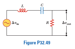
The resistor as shown represents the midrange speaker in a three-speaker system. Assume its resistance to be constant at 8.00 Ω. The source represents an audio amplifier producing signals of uniform amplitude ΔVmax = 10.0 V at all audio frequencies. The inductor and capacitor are to function as a band-pass filter with ΔVout/ΔVin = 1/2 at 200 Hz and at 4.00 × 10³ Hz. Determine the required values of (a) L and (b) C. Find (c) the maximum value of the ratio ΔVout/ΔVin; (d) the frequency f0 at which the ratio has its maximum value; (e) the phase shift between Δυin and Δυout
at 200 Hz, at f0, and at 4.00 × 10³ Hz; and (f) the average power transferred to the speaker at 200 Hz, at f0, and at 4.00 × 10³ Hz. (g) Recognizing that the diagram represents an RLC circuit driven by an AC source, find its quality factor.

Step by step
Solved in 2 steps


