
Videos
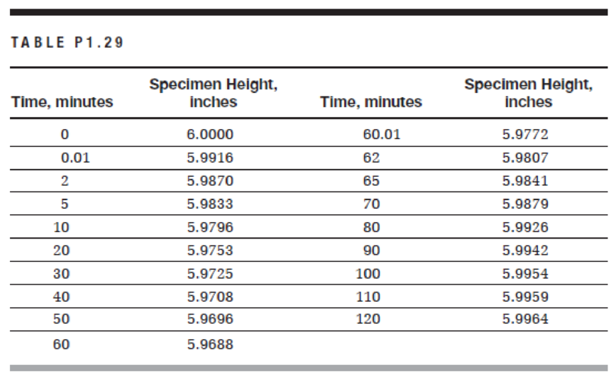
An asphalt concrete cylindrical specimen with a 4-in. diameter and a 6-in. height is subjected to an axial compressive static load of 150 lb for 1 hour, after which the load is removed. The test was performed at a temperature of 100°F. The height of the specimen was measured at different time intervals during loading and unloading for a total of 2 hours and produced the results shown in Table P1.29.
a. Using a spreadsheet program, plot the stress versus time and the strain versus time on two separate graphs.
b. How much is the elastic strain?
c. What is the permanent strain at the end of the experiment?
d. What is the phenomenon of the change of specimen height during static loading called? What is the phenomenon of the change of specimen height during unloading called?

Trending nowThis is a popular solution!

Chapter 1 Solutions
Materials for Civil and Construction Engineers (4th Edition)
Additional Engineering Textbook Solutions
Foundation Design: Principles and Practices (3rd Edition)
Database Concepts (7th Edition)
Mechanics of Materials (10th Edition)
Starting out with Visual C# (4th Edition)
Java: An Introduction to Problem Solving and Programming (7th Edition)
Java How to Program, Early Objects (11th Edition) (Deitel: How to Program)


- A contractor claims that the mean compressive strength for a concrete mix is 32.4 MPa and that it has a standard deviation of 2.8 MPa. If you break 16 cylinders and obtain a mean compressive strength of 30.3 MPa, would you believe the contractor’s claim? Why? (Hint: Use statistical t-test.)arrow_forwardA compact tension specimen is tested according to ASTM standard E399. The load displacement curve is shown in the Figure below with PQ= 120 kN (Type 1 curve). The specimen dimensions are B=0.5 cm, W=10 cm, and “a” =5 cm. If the materials yield stress is 600 MPa are the conditions correct for a valid K1C measurement? Please look up McEviley’s textbook on the thickness criterion for a valid fracture toughness value.arrow_forward1. A vertical pressure of 70 MPa is applied to an aluminum cube sample with a length of 10 cm on each side. The modulus of elasticity of aluminum is 70000 MPa and the Poisson ratio is 0.3. a) Find the new dimensions of the cube b) What will be the new dimensions if 70 MPa pressure is applied in the horizontal directions in addition to the 70 MPa pressure in the vertical direction?arrow_forward
- 15. A long proportional MS test specimen was subjected to tension. Determine (Modulus of - Modulus of Toughness - Elongation percentage) if you know that : Resilience a. b. Elongation = 0.12 mm at load 3 tons. & Elongation = 2.2 mm at load 5 tons. Load at proportional limit= 4.5 tons & Max. load = 7.5 tons Modulus of elasticity E = 2000 t\cm². Gage length after failure Li = 207 mm. C. d.arrow_forwardQI- A concrete cylindrical specimen 155 mm in diameter and 290 mm long is subjected to compressive loading up to failure. The following data shown in table below are obtained. Draw the stress- strain curve and determine: i) the concrete strength. ii) Initial Tangent Modulus. iii) Modulus of Elasticity. Iv) Secant Modulus at 90% of strength and v) State which type of stress strain behavior is this. Load, kN Deformation, mm×10* (Load - 8x16) (Deformation x 0.5x16) 222.5 103 413.1 206 635.2 324 730.4 378 856.1 432 953.6 486 1080.7 540 1171.2 756 1270.0 1025 1396.3 1395arrow_forwardGiven the image below. What is the maximum diameter of aggregate considering the narrowest dimension of the beam in cm if the value of c is 40cm and the value of e is 69cm? slab Oslab=10mm Obeam=25™m beam b earrow_forward
- A1 Copy the sketch of the tensile stress-strain test (Figure A1) results for a waisted metallic specimen and indicate the locations representing maximum stress (A), ultimate strain to failure (B), and 0.2% proof (yield) stress (C), and calculate the Young's modulus of the material. Figure A1 300 250 200 150 100 50 0 Stress (MPa) 0.2 0.4 0.6 8.0 Strain (%) 10.0arrow_forwardTwo 150 mm * 300 mm concrete cylinders with randomly oriented steelfiber contents of 0 and 2% by weight, respectively. After curing for 28 days,the specimens were subjected to increments of compressive loads until failure. The load versus deformation results were as shown in Table P7.45. Assuming that the gauge length is the whole specimen height, determine the following:a. The compressive stresses and strains for each specimen at each loadincrement.b. Plot stresses versus strains for the two specimens on one graph.c. The initial modulus of elasticity for each specimen.d. The ultimate strength for each specimen.e. The strain at failure for each specimen.f. Toughness. Curves may be approximated with a series of straight lines.g. Comment on the effect of adding fiber on the following:i. Modulus of elasticityii. Ultimate strengthiii. Ductilityiv. Toughnessarrow_forward150mm cylindrical concrete specimen was tested for tensile strength. When the applied load is 180,000N, the sample failed with a tensile strength of 2.55MPa. What is the length of the specimen in mm? Round off your answer to the nearest whole number.arrow_forward
- 7:50 ul LTE O A docs.google.com Choose the correct answer * During the tensile test, experiment on a sample of mild steel, data represented in the figure below was obtained with an initial diameter (do) of 0.505 inch. At failure, the reduced diameter (d) of the sample was 0.305 inch. Gauge Length (Lo) is 2 inches and final Gauge Length (L,) is 2.625 inches. Answer the questions below: Us 70 Tk LyP IR 50- FL PL ptiel linit AL or 6T P EL lastie lii UP per yied paint Lypi Lewer s us t uni mated streagth IR: Indicatul siregh Rupture TR True strugth Ruple fPL (propartimal timt) Direct strain & to to E strmin Cin/in) a b 1. Mild steel is: (a) brittle materials (b) ductile material (c) between the ductile and the brittle 2. Young's Modulus evaluates elasticity within the region from: (а) 0 - Proportional Limit. (b) Proportional Limit - Lower yield Point. (c) Lowerarrow_forwardA steel specimen of 300 mm length and 30 mm diameter is subjected to tensile test in a computerizedUTM. Under 54 kN of tensile load, the final length and diameter are observed as 300.112 mm and29.99634 mm respectively. Calculate (a) the Poission’s ratio and (b) the values of three moduli.arrow_forwardSeveral buildings have foundations made of material such as concrete. In fact, the compressive strength of concrete is a critical factor in providing a firm foundation of structures. The stress-strain diagram of concrete shown below has the points of failure as indicated by dots. (a)Determine the Young's modulus for this particular concrete under compression. See stress-strain diagram in figure 05. * Tenrle 10' Pa Bb 5.0 Compremve Tenale tren, 10 tren, 10 150 Cempreeren 'Pa Figure 05 O 25 GPa O 25 MPa O 25 KPa O 0.04 nPa O other:arrow_forward

 Structural Analysis (10th Edition)Civil EngineeringISBN:9780134610672Author:Russell C. HibbelerPublisher:PEARSON
 Principles of Foundation Engineering (MindTap Cou...Civil EngineeringISBN:9781337705028Author:Braja M. Das, Nagaratnam SivakuganPublisher:Cengage Learning
 Fundamentals of Structural AnalysisCivil EngineeringISBN:9780073398006Author:Kenneth M. Leet Emeritus, Chia-Ming Uang, Joel LanningPublisher:McGraw-Hill Education
 Traffic and Highway EngineeringCivil EngineeringISBN:9781305156241Author:Garber, Nicholas J.Publisher:Cengage Learning