
Concept explainers
Videos
A balanced, positive-sequence wye-connected source has Van = 240
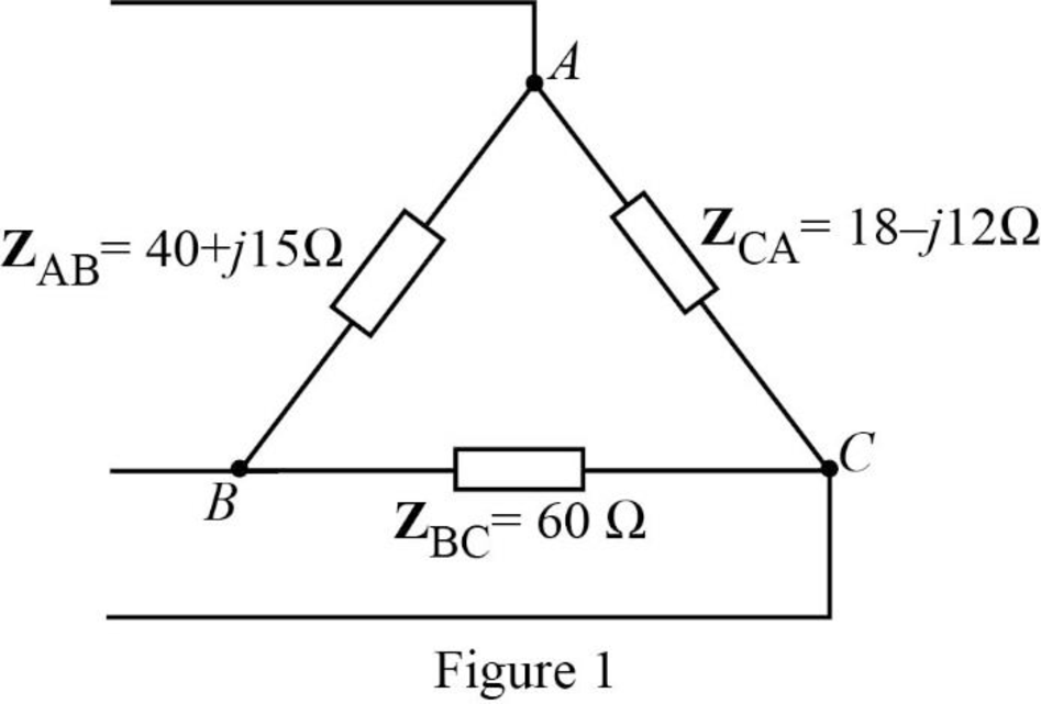
- (a) Calculate the line currents if ZAB = 40 + j15 Ω, ZBC = 60 Ω, ZCA = 18 − jl2 Ω.
- (b) Find the complex power supplied by the source.
a.
Calculate the line currents for the described circuit using PSpice.
Answer to Problem 48P
The value for the line currents
Explanation of Solution
Given data:
The phase voltage is
The transmission line impedance is
The value of the impedances
Formula used:
Write the formulae for the conversion of delta connected impedances to star connected impedances.
Here,
Write the expression for reactance of the inductor.
Here,
Write the expression for reactance of the capacitor.
Here,
Calculation:
The given unbalanced delta connected load is shown in Figure 1.
Substitute
Substitute
Substitute
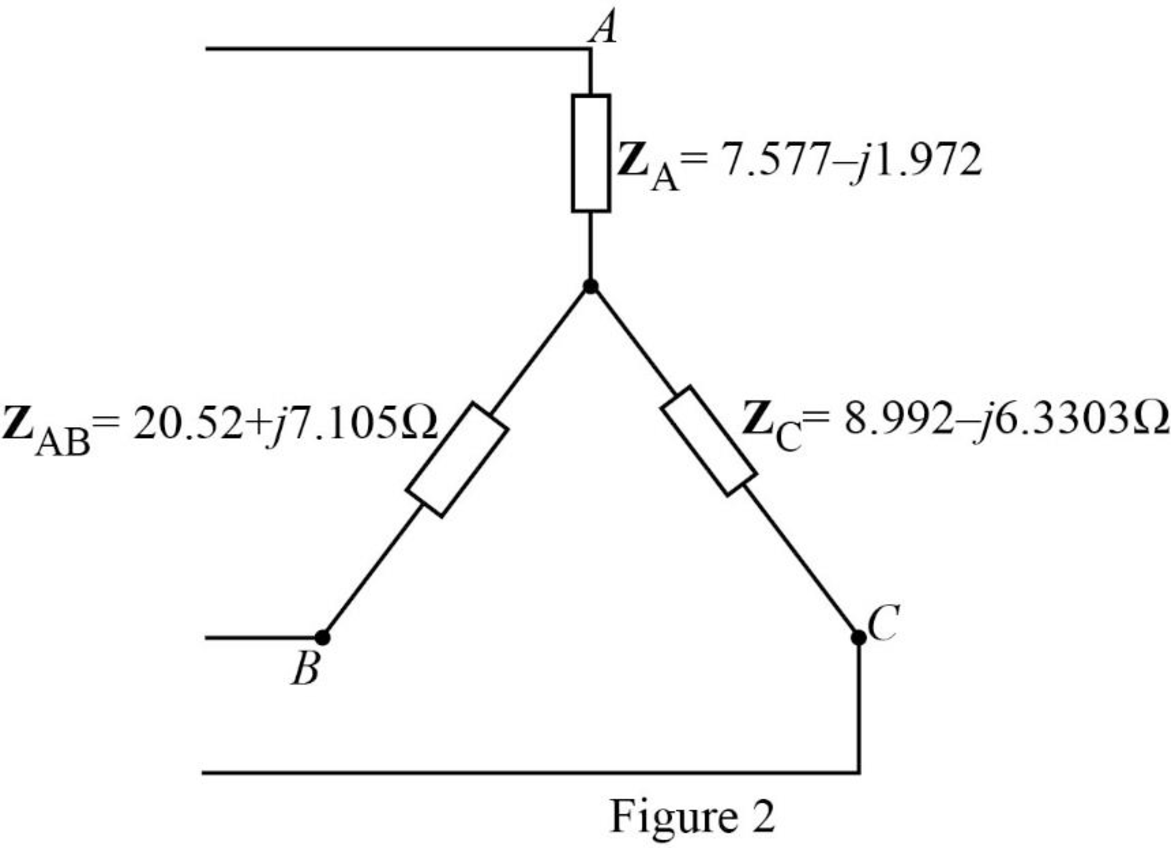
The transformed circuit is shown in Figure 2.
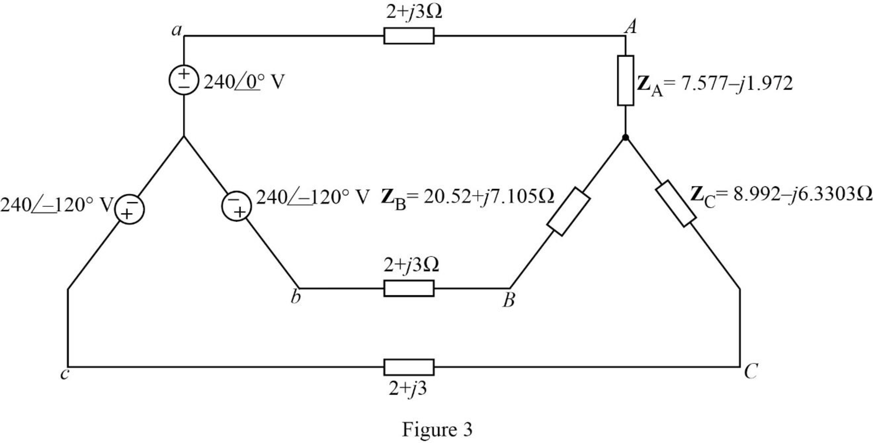
The given balanced wye-connected source supplies the unbalanced delta connected load is shown in Figure 3.
Let us assume that the value of the angular frequency,
Calculate the frequency as follows.
Substitute
Substitute
Substitute
Substitute
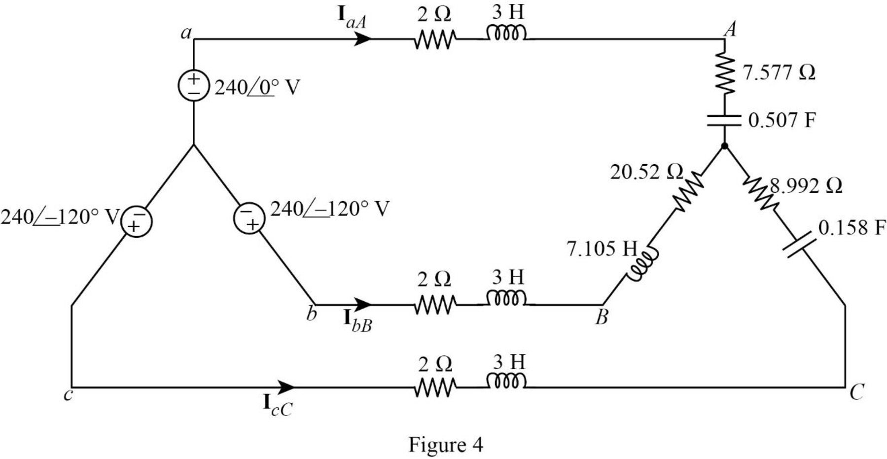
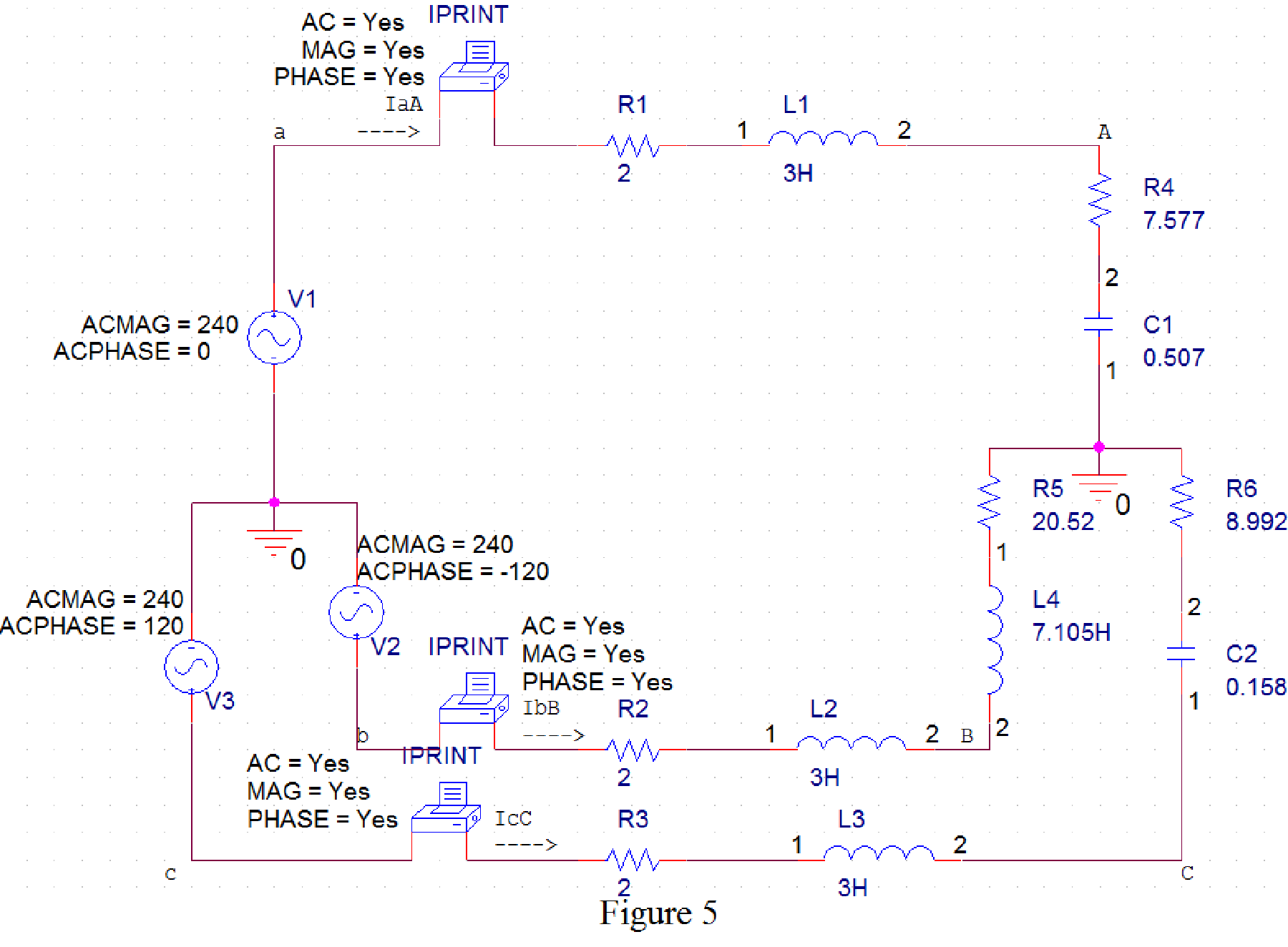
The time domain representation of Figure 3 is shown in Figure 4.
PSpice Simulation:
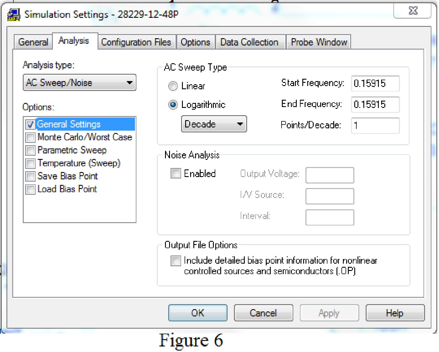
Draw Figure 4 in PSpice as shown in Figure 5.
Provide the simulation setting as shown in Figure 6.
The obtained results are given below.
FREQ IM(V_PRINT1) IP(V_PRINT1)
1.592E-01 2.492E+01 -6.124E+00
FREQ IM(V_PRINT2) IP(V_PRINT2)
1.592E-01 9.723E+00 -1.442E+02
FREQ IM(V_PRINT3) IP(V_PRINT3)
1.592E-01 2.094E+01 1.365E+02
The obtained line currents are given below.
Conclusion:
Thus, the value for the line currents
b.
Calculate the total complex power supplied by the source.
Answer to Problem 48P
The total complex power supplied by the source is
Explanation of Solution
Calculation:
Write the expression for complex power delivered by source
Substitute
Write the expression for complex power delivered by source
Substitute
Write the expression for complex power delivered by source
Substitute
Write the expression for total complex power supplied by the source.
Substitute
Conclusion:
Thus, the total complex power supplied by the source is
Want to see more full solutions like this?
Chapter 12 Solutions
Fundamentals of Electric Circuits
Additional Engineering Textbook Solutions
Engineering Electromagnetics
Principles Of Electric Circuits
Electrical Engineering: Principles & Applications (7th Edition)
Microelectronics: Circuit Analysis and Design
Programmable Logic Controllers
Electric machinery fundamentals


- A three-phase A-connected generator has an inter- nal impedance of 9 + j90 m2/þ. When the load is removed from the generator, the magnitude of the terminal voltage is 13,800 V. The generator feeds a A-connected load through a transmission line with an impedance of 20 + j180 m2/þ. The per-phase impedance of the load is 7.056 + j3.417 N. a) Construct a single-phase equivalent circuit. b) Calculate the magnitude of the line current. c) Calculate the magnitude of the line voltage at the terminals of the load. d) Calculate the magnitude of the line voltage at the terminals of the source.arrow_forwardA delta connected load with Zab=3 + j2 Ohm, Zbc=3 + j4 Ohm and Zca=2 + j3 Ohm are connected the end of a three-phase line as shown in the figure. The line impedance is 1+j2 Ohm per phase. The line is supplied from a three-phase source with line-to-line voltage of Vab=200.0/0° V rms. Taking the phase current vector lab as the reference vector, determine; (a) Line current Ia. (b) Total complex power supplied from the source. (c) Magnitude of the line-to-line voltage at the load terminal. ao- bo- Co- 1+j2 b aarrow_forward1. What is the main direct cause of reactive power in AC system? A. Resistance of transmission lines B. Inductance and capacitance in the loads C. Ideal transformer connected in the system D. Power produced by generator 2. "Reactive power in a system is dissipated generally as thermal energy?" A. TRUE B. FALSE 3. Which of the following statements are correct for three phase circuit: A. Sum of all the three phase currents is zero in unbalanced network B. Total power transfer to load is constant with time C. Neutral conductor is same size in terms of material used as in single phase conductors D. Net apparent power consumed is equal to real powerarrow_forward
- 5. The figure below shows two star connected loads with three phase power. The voltage source is 120Z0°. The loads are Z₁ = 10 + j4 № and Z₂ = 2 +j3 №. The cables are negligible. Calculate: a) the line and phase current. b) the real power from the source. c) the reactive power of the circuit. Is V N Z₁ Z₁ Z₁ Z₂ Z₂ N N Z₂arrow_forward20) Two AC generators A and B are in Parallel. Each generator has an emf of 1000V per phase and in phase, the phase impedance are ZA = 0.1+j2 ohms, ZB = 0.2+j3.2 ohms respectively. If the common load has an impedance of (2+j1) ohms per phase, solve the voltage per phase at the loadarrow_forwardThere is an installation with two equal three-phase loads of 150 kW each and a power factor of 0.9 in lagging. By connecting a pure reactive element in parallel, the reactive power at the input of the installation is 160 kVARS, with a lagging power factor. It can be said that:A)Capacitors were connected and the fp improved. B) Capacitors were connected and the fp improved. C) Reactors were connected and the fp improved. D)Reactors were connected and fp improved. E) None of the abovearrow_forward
- Two balanced three phase loads are connected in parallel, the loads are L1= 20 kW at 0.7 pf lead, and L2= 12 kVA at 0.9 pf lag. The loads are fed from a distribution line with an impedance of 0.05+j0.2 Q/P. The line to neutral voltage at the load end is 203 V and zero phase shift, the capacitance of A-connected capacitor bank that connected parallel to the loads to improve the power factor to unity in uF is; (f=60 Hz) O A. None B. 325.49 O C. 976.48 O D. 108.50 O E. 36.17arrow_forwardObtain the equivalent circuit of a 200/400 V, 50 Hz, single-phase transformcr from the following test data: O.C. test : 200 V, 0-7 A, 70 W .. on L.V. side S.C. test : 15 V, 10 A, 85 W Calculate the secondary voltage when delivering S kW at 08 p.f. lagging, the primary voltage being . on H.V. side 200 V. (R, = 57-14 Q ; X, = 330 2; R = 0-21 Q ; Xg, = 0-31 Q ; 3778 V)arrow_forwardIn a balanced Y-Y circuit shown in Figure 5, the magnitude of the phase voltage at the source is Vp = 2520 V (rms) and Van = 252020° V (rms). The load impedance is Zy = 135 + j55 Q per phase and the wire impedance is Zw=85 + j65 per phase. All the voltages and currents are in rms in this problem. (a) Find the phasors for line currents IA, IB, Ic in rms. (b) Find the load voltage VAN = IAZY. Also find VBN, and VCN. (c) Find the line voltages VAB, VBC, VCA at the load. (d) Find the complex power SL of the load. ZW ZY Van a A IA ZW ZY Vbn b В IB N ZW ZY Vcn IC Figure 5arrow_forward
- If Van = 200 / 60° V in the network of the figure given below, find the load phase currents IAB, IBC, and ICA. Please report your answer so the magnitude is positive and all angles are in the range of negative 180 degrees to positive 180 degrees. a A Three-phase, Y-connected generator (+) phase sequence b с j9 Q B 12 Q2 www 12 Q2 j9Q m j9 Q 12 Ω Carrow_forwardA balanced three-phase Delta connected voltage source supplies Delta connected three-phase symmetrical load through a three-phase line at 50 Hz as shown in the figure below. Please, answer the following using ZL=0.4+j 0.8 N and Zab = Zbc = Zca=10.3+j 14.1 N. A I a Zz Z. ca I 400 20° v +1 400Z-120° v Ic SOURCE LINÉ LOAD Part F: Calculate the reactive power of the three-phase Delta load in terms of VAr. 4002-240° varrow_forwardA three-phase A-connected generator has an inter- nal impedance of 0.6 + j4.8 N/4. When the load is removed from the generator, the magnitude of the terminal voltage is 34,500 V. The generator feeds a A-connected load through a transmission line with an impedance of 0.8 + j6.4 N/þ. The per-phase impedance of the load is 2877 – j864 N. a) Construct a single-phase equivalent circuit. b) Calculate the magnitude of the line current. c) Calculate the magnitude of the line voltage at the terminals of the load. d) Calculate the magnitude of the line voltage at the terminals of the source. e) Calculate the magnitude of the phase current in the load. f) Calculate the magnitude of the phase current in the source.arrow_forward
 Power System Analysis and Design (MindTap Course ...Electrical EngineeringISBN:9781305632134Author:J. Duncan Glover, Thomas Overbye, Mulukutla S. SarmaPublisher:Cengage Learning