
Loose Leaf for Engineering Circuit Analysis Format: Loose-leaf
9th Edition
ISBN: 9781259989452
Author: Hayt
Publisher: Mcgraw Hill Publishers
expand_more
expand_more
format_list_bulleted
Videos
Textbook Question
Chapter 14, Problem 2E
Compute the complex conjugate of each of the following expressions: (a) −1; (b) 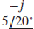 ; (c) 5e−j5 + 2ej3; (d)
  .
.
Expert Solution & Answer
Want to see the full answer?
Check out a sample textbook solution
Students have asked these similar questions
Calculate the energy stored in a capacitor at t= if the voltage
across it is.
Ans:
Given the waveform of the current in a 3H inductor as
shown in figure 4. Determine the inductor voltage and
sketch it.
K(0) (A)
0
Figure 4
1
2 3
Q1 (True/False):
A) The current through the capacitor is inversely proportional to the derivative of the voltage across it:
Is it true or false?
B) In a typical electronic circuit the capacitor blocks DC and couplest he AC to the next stage of the circuit:
Is it true or false?
C) The more the value of the stray capacitance , the better it is:
Is it true or false?
Find and plot the currents i(t), iz(t), and iz(t) in the circuit below given is(t) as shown in the plot.
Hint: First determine the equivalent inductance that can replace the three inductors. Next, find the
voltage across the current source, then, calculate the current in each inductor.
is (t)
1Hi(t)
10 mA
Dis(t)
ist)
5 H 3 is(t)
2 ms
4 ms
Chapter 14 Solutions
Loose Leaf for Engineering Circuit Analysis Format: Loose-leaf
Ch. 14.1 - Identify all the complex frequencies present in...Ch. 14.1 - Use real constants A, B, C, , and so forth, to...Ch. 14.2 - Let f (t) = 6e2t [u(t + 3) u(t 2)]. Find the (a)...Ch. 14.3 - Prob. 4PCh. 14.3 - Prob. 5PCh. 14.4 - Prob. 6PCh. 14.4 - Prob. 7PCh. 14.4 - Prob. 8PCh. 14.4 - Prob. 9PCh. 14.5 - Prob. 10P
Ch. 14.5 - Prob. 11PCh. 14.5 - Prob. 12PCh. 14.6 - Prob. 13PCh. 14.7 - Prob. 14PCh. 14.7 - Prob. 15PCh. 14.8 - Find the mesh currents i1 and i2 in the circuit of...Ch. 14.8 - Prob. 17PCh. 14.8 - Prob. 18PCh. 14.9 - Using the method of source transformation, reduce...Ch. 14.9 - Prob. 20PCh. 14.10 - The parallel combination of 0.25 mH and 5 is in...Ch. 14.11 - Prob. 22PCh. 14.11 - Prob. 23PCh. 14.11 - Prob. 24PCh. 14.11 - Prob. 25PCh. 14.12 - Prob. 26PCh. 14 - Determine the conjugate of each of the following:...Ch. 14 - Compute the complex conjugate of each of the...Ch. 14 - Several real voltages are written down on a piece...Ch. 14 - State the complex frequency or frequencies...Ch. 14 - For each of the following functions, determine the...Ch. 14 - Use real constants A, B, , , etc. to construct the...Ch. 14 - The following voltage sources AeBt cos(Ct + ) are...Ch. 14 - Prob. 8ECh. 14 - Compute the real part of each of the following...Ch. 14 - Your new assistant has measured the signal coming...Ch. 14 - Prob. 11ECh. 14 - Prob. 12ECh. 14 - Prob. 13ECh. 14 - Prob. 14ECh. 14 - Prob. 15ECh. 14 - Prob. 16ECh. 14 - Determine F(s) if f (t) is equal to (a) 3u(t 2);...Ch. 14 - Prob. 18ECh. 14 - Prob. 19ECh. 14 - Prob. 20ECh. 14 - Prob. 21ECh. 14 - Evaluate the following: (a)[(2t)]2 at t = 1;...Ch. 14 - Evaluate the following expressions at t = 0: (a)...Ch. 14 - Prob. 24ECh. 14 - Prob. 25ECh. 14 - Prob. 26ECh. 14 - Prob. 27ECh. 14 - Prob. 28ECh. 14 - Prob. 29ECh. 14 - Prob. 30ECh. 14 - Prob. 31ECh. 14 - Prob. 32ECh. 14 - Prob. 33ECh. 14 - Obtain the time-domain expression which...Ch. 14 - Prob. 35ECh. 14 - Prob. 36ECh. 14 - Prob. 37ECh. 14 - Prob. 38ECh. 14 - Prob. 39ECh. 14 - Prob. 40ECh. 14 - Prob. 41ECh. 14 - Obtain, through purely legitimate means, an...Ch. 14 - Prob. 43ECh. 14 - Employ the initial-value theorem to determine the...Ch. 14 - Prob. 45ECh. 14 - Prob. 46ECh. 14 - Prob. 47ECh. 14 - Prob. 48ECh. 14 - Prob. 49ECh. 14 - Prob. 52ECh. 14 - Determine v(t) for t 0 for the circuit shown in...Ch. 14 - Prob. 54ECh. 14 - Prob. 55ECh. 14 - For the circuit of Fig. 14.54, (a) draw both...Ch. 14 - Prob. 58ECh. 14 - Prob. 59ECh. 14 - Prob. 60ECh. 14 - For the circuit shown in Fig. 14.58, let is1 =...Ch. 14 - Prob. 63ECh. 14 - Prob. 64ECh. 14 - For the circuit shown in Fig. 14.62, determine the...Ch. 14 - Prob. 67ECh. 14 - Prob. 68ECh. 14 - Determine the poles and zeros of the following...Ch. 14 - Use appropriate means to ascertain the poles and...Ch. 14 - Prob. 71ECh. 14 - For the network represented schematically in Fig....Ch. 14 - Prob. 73ECh. 14 - Prob. 74ECh. 14 - Prob. 75ECh. 14 - Prob. 76ECh. 14 - Prob. 77ECh. 14 - Prob. 78ECh. 14 - Prob. 79ECh. 14 - Prob. 80ECh. 14 - Prob. 81ECh. 14 - Prob. 82ECh. 14 - Design a circuit which produces the transfer...Ch. 14 - Prob. 84ECh. 14 - Prob. 85ECh. 14 - An easy way to get somebodys attention is to use a...Ch. 14 - Prob. 87E
Additional Engineering Textbook Solutions
Find more solutions based on key concepts
Design an ideal inverting op-amp circuit such that the voltage gain is Av=25 . The maximum current in any resis...
Microelectronics: Circuit Analysis and Design
Explain the main function of each of the following major components of a PLC: a. Processor module (CPU) b. I/O ...
Programmable Logic Controllers
Does the severity of an electric shock increase ordecrease with eh of the following changes? a. A decrease in t...
Electric Motors and Control Systems
Analog Voltmeter Design Figure P2-98(a) shows a voltmeter circuit consisting of a D'Arsonval meter, two series ...
ANALYSIS+DESIGN OF LINEAR CIRCUITS(LL)
Electric power systems provide energy in a variety of commercial and industrial settings. Make a list of system...
Principles and Applications of Electrical Engineering
A constant voltage of 10V is applied to a 50H inductance, as shown in Figure P3.51 Figure P3 51 The current in ...
Electrical Engineering: Principles & Applications (7th Edition)
Knowledge Booster


Learn more about
Need a deep-dive on the concept behind this application? Look no further. Learn more about this topic, electrical-engineering and related others by exploring similar questions and additional content below.Similar questions
- The current in a 10-mH inductor has the waveform shown i(t) (mA) 20 2 4 t (ms) a) the voltage induced across the inductor between 0 to 2ms is b) the voltage induced across the inductor between 2 to 4ms is Answer must be in numeral form. No decimal point. mV mVarrow_forwardState the characteristic equation for the system, including what it equals. Determine the eigenvalue(s). State whether the system is internally stable, marginally stable, or unstable. And choose the correct plotarrow_forwardFor the circuit shown Figure 3, Calculate the expression of the Va(t) assume the initial value of inductor current is 2A and the initial value voltage capacitor is zero. IH 10 20 10cos5t 20 0.5F Ve Figure 3arrow_forward
- 13 i(1) (A) I (s) If the current flowing through a mH inductor has the waveform shown, what is the voltage at t = 2.5s?arrow_forwardA coil having a 240V source has a current of 10.5 A when the frequency is set to 60 Hz. When the frequency is changed to 16 Hz, the resulting current is now 15.5 A. Find the inductance, L, of the coil (in mH). (use 2 decimal places. No unit required)arrow_forwardFigure 1(a) shows the voltage, Vout measured across the capacitor C2 in Figure 1(b). Find the expression of current, I(t) for 0 ms < t< 6 ms. Draw the waveform of this current.arrow_forward
- A 0.8-F capacitor is connected in series with a 7-ohm resistor. If the connection is energized from a 10-V DC source, determine the voltage (in volts) across the capacitor at t = 2.5 ms. The initial charge is 150 mC. Express your answers accurate to four decimal places. No need to put the units. Do not put spaces.arrow_forwardIn the given circuit; an initial voltage V,-10 V exists across the capacitor. Calculate a) The time constant of the circuit b) The voltage across the capacitor after t= 2t c) The current through the capacitor after t= 2t 4T mfarrow_forward(b) A medical technology company is designing a new portable defibrillator for reviving patients whose heart has stopped. The capacitor in the device will be charged to 2000 V and is required to deliver 400 J of energy on discharge. i) Calculate the capacitance required for this capacitor ii) The conducting plates of the capacitor must have an area of 5 m² and be separated by an insulator with thickness of 0.05 mm. Determine the value of dielectric constant for the insulator between the capacitor parallel plates to deliver the intended energy to the patientarrow_forward
- Q1. The initial values of i, and iz in the circuit shown are +3 A and -5 A, respectively. The voltage terminals of the parallel inductors for tt > 0 is –30e-5t (a) If the parallel inductors are replaced by a single inductor, what is its inductance? (b) What is the initial current and its reference direction in the equivalent inductor? (c) Use the equivalent inductor to find i(t). (d) Find i, (t) and iz(t). Verify that the solutions for i, (t),iz (t) and i(t) satisfy Kirchhoff's current law. i(1) i,(1)360 mH i(13240 mH Figure 1arrow_forwardDuring the charging process of the RC- circuit, the current changes as a function of time as shown. Knowing that the resistance R= 25k2, then the capacitor has a value of: I quA) 100 3. 63 37 t (sec) 23.1 50 Select one: a. 500µF b. 2000µF c. 1000µF d. We can't determinearrow_forwardFor function f(t) = 5 sin(2t) show analytically & graphically the function form subject to shift upwards by 5 units shift in time domain by 5 units left. Please answer in typing format and draw diagram on paper and cleanarrow_forward
arrow_back_ios
SEE MORE QUESTIONS
arrow_forward_ios
Recommended textbooks for you
 Introductory Circuit Analysis (13th Edition)Electrical EngineeringISBN:9780133923605Author:Robert L. BoylestadPublisher:PEARSON
 Delmar's Standard Textbook Of ElectricityElectrical EngineeringISBN:9781337900348Author:Stephen L. HermanPublisher:Cengage Learning
 Programmable Logic ControllersElectrical EngineeringISBN:9780073373843Author:Frank D. PetruzellaPublisher:McGraw-Hill Education
 Fundamentals of Electric CircuitsElectrical EngineeringISBN:9780078028229Author:Charles K Alexander, Matthew SadikuPublisher:McGraw-Hill Education
 Electric Circuits. (11th Edition)Electrical EngineeringISBN:9780134746968Author:James W. Nilsson, Susan RiedelPublisher:PEARSON
 Engineering ElectromagneticsElectrical EngineeringISBN:9780078028151Author:Hayt, William H. (william Hart), Jr, BUCK, John A.Publisher:Mcgraw-hill Education,
Introductory Circuit Analysis (13th Edition)
Electrical Engineering
ISBN:9780133923605
Author:Robert L. Boylestad
Publisher:PEARSON
Delmar's Standard Textbook Of Electricity
Electrical Engineering
ISBN:9781337900348
Author:Stephen L. Herman
Publisher:Cengage Learning
Programmable Logic Controllers
Electrical Engineering
ISBN:9780073373843
Author:Frank D. Petruzella
Publisher:McGraw-Hill Education
Fundamentals of Electric Circuits
Electrical Engineering
ISBN:9780078028229
Author:Charles K Alexander, Matthew Sadiku
Publisher:McGraw-Hill Education
Electric Circuits. (11th Edition)
Electrical Engineering
ISBN:9780134746968
Author:James W. Nilsson, Susan Riedel
Publisher:PEARSON
Engineering Electromagnetics
Electrical Engineering
ISBN:9780078028151
Author:Hayt, William H. (william Hart), Jr, BUCK, John A.
Publisher:Mcgraw-hill Education,
Inductors Explained - The basics how inductors work working principle; Author: The Engineering Mindset;https://www.youtube.com/watch?v=KSylo01n5FY;License: Standard Youtube License