
University Physics Volume 2
18th Edition
ISBN: 9781938168161
Author: OpenStax
Publisher: OpenStax
expand_more
expand_more
format_list_bulleted
Videos
Textbook Question
thumb_up100%
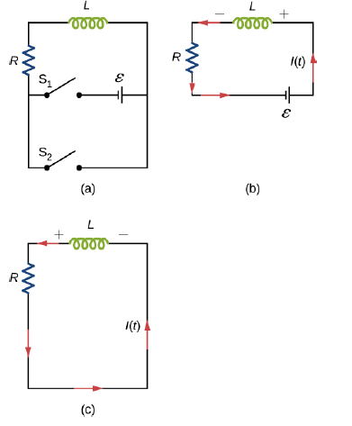
Chapter 14, Problem 54P
The current in the RL circuit shown here increases to 40% of its steady-state value in 2.0 s. What is the time constant of the circuit?
Expert Solution & Answer
Want to see the full answer?
Check out a sample textbook solution
Students have asked these similar questions
The current in the RL circuit shown below reaches half its maximum value in 0.5 ms after the switch S1 is
thrown. Determine (a) the time constant of the circuit and (b) the resistance of the circuit if
L = 200 mH.
R
Hints
a. The time constant is TL =
ms.
b. The resistance R is
Ω.
The current in the RL circuit shown below reaches one-fourth its maximum value in 2.75 ms after the switch s, is thrown.
R
(a) Determine the time constant of the circuit (in ms).
ms
(b) Determine the resistance of the circuit (in 0) if L = 200 mH.
The battery terminal voltage in the figure below is E = 8.30 V and the current I reaches half its maximum value of 5.00 A
at t = 0.200 s after the switch is closed.
HINT
S
+
E
S
Apply the expression for the current in an RL circuit.
V
R
(a) Calculate the time constant 7 (in s).
V
ele
Click the hint button again to remove this hint.
(b) What is the potential difference (in V) across the inductor at t = 0.200 s?
(c) What is the potential difference (in V) across the inductor in the instant after the switch is closed at t = 0?
Chapter 14 Solutions
University Physics Volume 2
Ch. 14 - Check Your Understanding. A current...Ch. 14 - Check Your Understanding. Current flows through...Ch. 14 - Check Your Understanding. A changing current...Ch. 14 - Check Your Understanding (a) Calculate the...Ch. 14 - Check Your Understanding (a) What is the magnetic...Ch. 14 - Check Your Understanding How much energy is stored...Ch. 14 - Check Your Understanding Verify that RC and L/R...Ch. 14 - Check Your Understanding (a) If the current in the...Ch. 14 - Check Your Understanding For the circuit of in...Ch. 14 - Check Your Understanding The angular frequency of...
Ch. 14 - Check Your Understanding In an RLC circuit, L =...Ch. 14 - Show that N m /l and el(dl/dt), which are both...Ch. 14 - A 10-H inductor carries a current of 20 A....Ch. 14 - The ignition circuit of an automobile is powered...Ch. 14 - When the current through a large inductor is...Ch. 14 - Does self-inductance depend on the value of the...Ch. 14 - Would the self-inductance of a 1.0 m long, tightly...Ch. 14 - Discuss how you might determine the-inductance per...Ch. 14 - The self-inductance of a coil is zero if there is...Ch. 14 - How does the self- inductance per unit length near...Ch. 14 - Solve that I I 2 /2 has units of energy.Ch. 14 - Use Lenz’s law to explain why the initial current...Ch. 14 - When the current in the RL circuit of Figure...Ch. 14 - Does the time required for the current in an RL...Ch. 14 - An inductor is connected across the terminals of a...Ch. 14 - At what time is the voltage across the inductor of...Ch. 14 - In the simple RL circuit of Figure 14.12(b), can...Ch. 14 - If emf of the battery of Figure 14.12(b) is...Ch. 14 - A steady current flows through a circuit with a...Ch. 14 - Describe how the currents through R1and R2, shown...Ch. 14 - Discuss possible practical applications of RL...Ch. 14 - Do Kirchhoff’s rules apply to circuits that...Ch. 14 - Can a circuit e1eent have both capacitance and...Ch. 14 - In an LC circuit, what determines the frequency...Ch. 14 - When a wire is connected between the two ends of a...Ch. 14 - Describe what effect the resistance of the...Ch. 14 - Suppose you wanted to design an LC circuit with a...Ch. 14 - A radio receiver uses an RLC circuit to pick out...Ch. 14 - When the current in one coi1 changes at a rate of...Ch. 14 - An emf of 9.7 × 10⁻³ V is induced in a coil while...Ch. 14 - Two coils close to each other have a mutual...Ch. 14 - A coil of 40 turns is wrapped around a long...Ch. 14 - A 600-turn solenoid is 0.55 m long and 4.2 cm in...Ch. 14 - A toroidal coil has a mean radius of 16 cm and a...Ch. 14 - A solenoid of N1turns has length l1and radius R1,...Ch. 14 - An emf of 0.40 V is induced across a coil when the...Ch. 14 - The current shown in part (a) below is increasing,...Ch. 14 - What is the rate at which the current though a...Ch. 14 - When a camera uses a flash, a fully charged...Ch. 14 - A coil with a self-inductance of 2.0 H carries a...Ch. 14 - A solenoid 50 cm long is wound with 500 turns of...Ch. 14 - A coil with a self-inductance of 3.0 H carries a...Ch. 14 - The current I(t) through a 5.0-mH inductor varies...Ch. 14 - A long, cylindrical solenoid with 100 turns per...Ch. 14 - Suppose that a rectangular toroid has 2000...Ch. 14 - What is the self-inductance per meter of a coaxial...Ch. 14 - At the instant a current of 0.20 A is flowing...Ch. 14 - Suppose that a rectangular toroid has 2000...Ch. 14 - Solenoid A is tightly wound while solenoid B has...Ch. 14 - A 10-H inductor carries a current of 20 A. How...Ch. 14 - A coil with a self-inductance of 3.0 H and a...Ch. 14 - A current of 1.2 A is flowing in a coaxial cable...Ch. 14 - In Figure 14.12, =12V , L = 20 mH, and R=5.0....Ch. 14 - For the circuit shown below, =20V , L = 4.0 mH,...Ch. 14 - The current in the RL circuit shown here increases...Ch. 14 - How long after switch S1 is thrown does it take...Ch. 14 - Examine the circuit shown below in part (a)....Ch. 14 - The current in the RL circuit shown below reaches...Ch. 14 - Consider the circuit shown below. Find l1, l2and...Ch. 14 - For the circuit shown below, =50V , R1= 10 , and...Ch. 14 - For the circuit shown below, find the current...Ch. 14 - Show that for the circuit shown below, the initial...Ch. 14 - A 5000-pF capacitor is charged to 100 V and then...Ch. 14 - The self-inductance and capacitance of an LC...Ch. 14 - What is the self-inductance of an LC circuit that...Ch. 14 - In an oscillating LC circuit the maximum charge on...Ch. 14 - The self-inductance and capacitance of an...Ch. 14 - In an oscillating LC circuit, the maximum charge...Ch. 14 - In the circuit shown below, S1is opened and S2is...Ch. 14 - An LC circuit in an AM tuner (in a car stereo)...Ch. 14 - In an oscillating RLC circuit, R=5.0 ,. L=5.0mH ,...Ch. 14 - In an oscillating RLC circuit with L = 10 mH, C =...Ch. 14 - What resistance R must be connected in series with...Ch. 14 - Show that the self-inductance per unit length of...Ch. 14 - Two long, parallel wires cy equal currents in...Ch. 14 - A small, rectangular single loop of wire with...Ch. 14 - Suppose that a cylindrical solenoid is wrapped...Ch. 14 - A solenoid with 4 x 10⁷turns/m has an iron core...Ch. 14 - A rectangular toroid with inner radius R1= 7.0cm,...Ch. 14 - The switch S of the circuit shown below is closed...Ch. 14 - In an oscillating RLC circuit, R = 7.0 L. = 10...Ch. 14 - A 25.0-H inductor has 100 A of current turned off...Ch. 14 - A coaxial cable has an inner conductor of radius...Ch. 14 - In a damped oscillating circuit the energy is...Ch. 14 - The switch in the circuit shown below is closed at...Ch. 14 - A square loop of side 2 cm is placed 1 cm from a...Ch. 14 - A rectangular copper ring, of mass 100 g and...
Additional Science Textbook Solutions
Find more solutions based on key concepts
25.4 and 25.5 Frequency, wavelength, and the electromagnetic spectrum and Mathematical description of EM waves ...
College Physics
34. (II) A grinding wheel is a uniform cylinder with a radius of 8.50 cm and a mass of 0.380 kg. Calculate (a) ...
Physics: Principles with Applications
Choose the best answer to each of the following. Explain your reasoning. How does a but Jupiter differ from Jup...
The Cosmic Perspective Fundamentals (2nd Edition)
17. What is the tension in the rope of Figure EX7.17?
Figure EX7.17
Physics for Scientists and Engineers: A Strategic Approach, Vol. 1 (Chs 1-21) (4th Edition)
Knowledge Booster


Learn more about
Need a deep-dive on the concept behind this application? Look no further. Learn more about this topic, physics and related others by exploring similar questions and additional content below.Similar questions
- The current through a 50-Q resistor is I = 0.80 sin (240 t). What is the rms current (in A)?arrow_forwardIn the circuit shown in the figure, Rị = 20.0 N, R2 = 30.0 N, R3 = 40.0 N, L = 15.0 H %3D and e = 100 V. What is the current i in units of ampere at t = 0.700 s after the switch is closed. R1 R3 R2 000arrow_forwardThe current in a single-loop circuit with one resistance R is 5.0 A.When an additional resistance of 2.0 is inserted in series with R, the current drops to 4.0 A.What is R?arrow_forward
- The current in an RL circuit drops from 1.0 A to 10 mA in the first second following removal of the battery from the circuit. If L is 10 H, find the resistance R in the circuit.arrow_forwardThe current in a series RL circuit increases to 20% of its final value in 3.1 ms. If L = 1.8 mH, what’s the resistance?arrow_forwardUseful Constants: k = 9.00 × 10º Nm² C2 8.85 x 10⁻¹² C² Nm2 %3D e = 1.6 x 10⁻¹⁹ C me = 9.11 x 10 mp = 1.67 × 10⁻²⁷kg %3D -27 mn = 1.68 x 10 %3Darrow_forward
- 9. In the circuit shown, assume the battery emf is 20.0 V, R = 1.00M, and C = 2.00µF. The switch is close t = 0. At what time t will the voltage across the capacitor be 15.0 V? R www ε Using the circuit shown in question number 9, find the current at time t where the voltage across the capa be 15.0 V?arrow_forwardProblem # 08 Find the equivalent capacitance between points A and B of the given circuit B 3.5 uF 5.0 µF 1.5 μF 8.0 µF 2.5 μF 0.75 µF 15 uF B.5 μFarrow_forwardIn the circuit to the right, & = 1.2kV, C = 6.5 µF, and R₁ = R₂ R3 = R = 0.73 M. With C completely uncharged, switch S is sud- denly closed at t = 0. Remember to draw equivalent circuits to help with the analysis! R₁ -£8 S اقع www R₂ R₂ Fww (a) At t = 0, what is the voltage across the capacitor? How are the voltages across R3 and R₂ related? (b) At t= 0, what are the currents in each resistor? (c) For t → ∞o, what are the currents in each resistor? (d) For t→ ∞o, what are the voltages across each resistor? (e) For t → ∞, what is the voltage across the capacitor? (f) Once the circuit has nearly reached equilibrium, the switch is reopened. What is the current in each resistor right after the switch is reopened? The equivalent circuit will be super useful here; note that when we change the circuit by opening the switch, the capacitor is no longer in steady state - do not assume its current is zero! (g) How long after the switch is reopened does it take for the current in R3 to drop to…arrow_forward
- The remaining circuit quantities may change instantaneously as required by Kirchhoff's rules. Q in uC immediately after the switch ( t = 0 + ), in that order.arrow_forwardDischarging Capacitor: Kirchoff's loop rule applied to the discharging capacitor circuit gives Q ΣAV₁ = loop = IR- = 0 The current is leaving the positive plate so I = -dQ/dt = -CdAVc/dt. Substituting this into loop rule gives a differential equation for Q(t): RC + AVc = 0 dAvc dt This is the simplest differential equation you will learn in your differential equations class. The solution for the differential equation for AVC (t) is an exponential: R www C AV (t) = AV e-t/(RC) (discharging) where AV, is the voltage across the capacitor when discharge begins (t = 0). The quantity Tc = RC has dimensions of time and is called the time constant of the circuit. It describes how long it takes for the capacitor to charge or discharge. 2. Show that a ohm farad is the same as a second. Show steps.arrow_forwarda. Consider the current configuration shown below. What is the magnitude of the cur- rent in the wire marked with a question mark? Is the current entering or leaving the node? 2.20 A 1.40 A 1.50 A- Current configurations for #1d b. Consider the single loop circuit shown below. Calculate the current which flows in the circuit. Is the current in the clockwise or the counterclockwise direction? 120 2 90 Ω 5.5 V 180 Ω Single loop circuit configurations for #1barrow_forward
arrow_back_ios
SEE MORE QUESTIONS
arrow_forward_ios
Recommended textbooks for you

What is Electromagnetic Induction? | Faraday's Laws and Lenz Law | iKen | iKen Edu | iKen App; Author: Iken Edu;https://www.youtube.com/watch?v=3HyORmBip-w;License: Standard YouTube License, CC-BY