
Statics and Mechanics of Materials (5th Edition)
5th Edition
ISBN: 9780134382593
Author: Russell C. Hibbeler
Publisher: PEARSON
expand_more
expand_more
format_list_bulleted
Concept explainers
Videos
Textbook Question
Chapter 14.3, Problem 35P
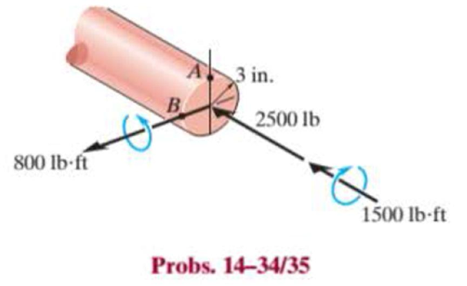
The internal loadings at a cross section through the 6-in.-diameter drive shaft of a turbine consist of an axial force of 2500 lb, a bending moment of 800 lb·ft, and a torsional moment of 1500 lb·ft. Determine the principal stresses at point B. Also calculate the maximum in-plane shear stress at this point.
Expert Solution & Answer
Want to see the full answer?
Check out a sample textbook solution
Students have asked these similar questions
The internal loadings at a cross section through the 6-in.-diameter drive shaft of a turbine consist of an axial force of 2500 lb, a bending moment of 800 lb # ft, and a torsional moment of 1500 lb # ft. Determine the principal stresses at point B. Also calculate the maximum in-plane shear stress at this point.
6. The figure below shows the geometry and loading of segment of a crankshaft. The diameter of the
upper shaft is 20mm. Determine the principal stresses and the maximum shear stress at point A, which
is located on the surface of the upper shaft at the zo axis.
b-80 mm
Xo
bz = 120 mm
by- 40 mm
P-LOKN
The 40-mm diameter solid shaft ACBD is supported by two bearings at A
and B. Due to the transmission of power to and from the shaft, the belts of
the pulleys are subjected to the tension forces shown in the figure below.
1-Draw the moment and shear diagrams on the y z and y x planes
2-Determine the location and magnitude of the maximum bending
(normal) stress.
Hint draw the shaft cross section at that location and think of the
associated stresses.
0.050 m
300 N
0.250 m
200 N
550 N
0.250 m
400 N
150m
D 0.075 m
Chapter 14 Solutions
Statics and Mechanics of Materials (5th Edition)
Ch. 14.3 - In each ease, the state of stress x, y, xy...Ch. 14.3 - Given the state of stress shown on the element,...Ch. 14.3 - Determine the normal stress and shear stress...Ch. 14.3 - Prob. 2FPCh. 14.3 - Determine the equivalent state of stress on an...Ch. 14.3 - Prob. 4FPCh. 14.3 - The beam is subjected to the load at its end....Ch. 14.3 - Prob. 6FPCh. 14.3 - Prove that the sum of the normal stresses x+y=x+y...Ch. 14.3 - Determine the stress components acting on the...
Ch. 14.3 - Determine the stress components acting on the...Ch. 14.3 - Determine the normal stress and shear stress...Ch. 14.3 - Determine the normal stress and shear stress...Ch. 14.3 - Prob. 6PCh. 14.3 - Prob. 7PCh. 14.3 - Determine the stress components acting on the...Ch. 14.3 - Determine the stress components acting on the...Ch. 14.3 - Determine the stress components acting on the...Ch. 14.3 - Determine the equivalent state of stress on an...Ch. 14.3 - Prob. 12PCh. 14.3 - Determine the stress components acting on the...Ch. 14.3 - Determine (a) the principal stresses and (b) the...Ch. 14.3 - Prob. 15PCh. 14.3 - Prob. 16PCh. 14.3 - Prob. 17PCh. 14.3 - Prob. 18PCh. 14.3 - Prob. 19PCh. 14.3 - Prob. 20PCh. 14.3 - Prob. 21PCh. 14.3 - The state of stress at a point in a member is...Ch. 14.3 - The wood beam is subjected to a load of 12 kN. If...Ch. 14.3 - Prob. 24PCh. 14.3 - The internal loadings at a section of the beam are...Ch. 14.3 - The internal loadings at a section of the beam are...Ch. 14.3 - Prob. 27PCh. 14.3 - Prob. 28PCh. 14.3 - The beam has a rectangular cross section and is...Ch. 14.3 - A paper tube is formed by rolling a cardboard...Ch. 14.3 - Prob. 31PCh. 14.3 - The 2-in.-diameter drive shaft AB on the...Ch. 14.3 - Determine the principal stresses in the...Ch. 14.3 - The internal loadings at a cross section through...Ch. 14.3 - The internal loadings at a cross section through...Ch. 14.3 - Prob. 36PCh. 14.3 - The steel pipe has an inner diameter of 2.75 in....Ch. 14.3 - Prob. 38PCh. 14.3 - The wide-flange beam is subjected to the 50-kN...Ch. 14.3 - Prob. 40PCh. 14.3 - The box beam is subjected to the 26-kN force that...Ch. 14.3 - The box beam is subjected to the 26-kN force that...Ch. 14.4 - Use Mohrs circle to determine the normal stress...Ch. 14.4 - Prob. 8FPCh. 14.4 - Prob. 9FPCh. 14.4 - Prob. 10FPCh. 14.4 - Prob. 11FPCh. 14.4 - Prob. 12FPCh. 14.4 - Solve Prob. 142 using Mohrs circle. 14-2.Determine...Ch. 14.4 - Solve Prob. 143 using Mohrs circle. 143.Determine...Ch. 14.4 - Determine the stress components acting on the...Ch. 14.4 - Solve Prob. 1410 using Mohrs circle. 149.Determine...Ch. 14.4 - Solve Prob. 1415 using Mohrs circle. 1415.The...Ch. 14.4 - Solve Prob. 1416 using Mohrs circle....Ch. 14.4 - Prob. 49PCh. 14.4 - Determine (a) the principal stresses and (b) the...Ch. 14.4 - Determine (a) the principal stresses and (b) the...Ch. 14.4 - Determine the equivalent state of stress if an...Ch. 14.4 - Draw Mohrs circle that describes each of the...Ch. 14.4 - Draw Mohrs circle that describes each of the...Ch. 14.4 - Determine (a) the principal stresses and (b) the...Ch. 14.4 - Determine (a) the principal stress and (b) the...Ch. 14.4 - Determine (a) the principal stresses and (b) the...Ch. 14.4 - Determine (a) the principal stresses and (b) the...Ch. 14.4 - Determine (a) the principal stresses and (b) the...Ch. 14.4 - Prob. 60PCh. 14.4 - The grains of wood in the board make an angle of...Ch. 14.4 - The post is fixed supported at its base and a...Ch. 14.4 - Determine the principal stresses, the maximum...Ch. 14.4 - The thin-walled pipe has an inner diameter of 0.5...Ch. 14.4 - The frame supports the triangular distributed load...Ch. 14.4 - The frame supports the triangular distributed load...Ch. 14.4 - Prob. 67PCh. 14.4 - The pedal crank for a bicycle has the cross...Ch. 14.4 - A spherical pressure vessel has an inner radius of...Ch. 14.4 - The cylindrical pressure vessel has an inner...Ch. 14.4 - Prob. 71PCh. 14.4 - Determine the principal stress at point D, which...Ch. 14.4 - If the box wrench is subjected to the 50 lb force,...Ch. 14.4 - If the box wrench is subjected to the 50-lb force,...Ch. 14.4 - Prob. 75PCh. 14.5 - Draw the three Mohrs circles that describe each of...Ch. 14.5 - Draw the three Mohrs circles that describe the...Ch. 14.5 - Draw the three Mohrs circles that describe the...Ch. 14.5 - Determine the principal stresses and the absolute...Ch. 14.5 - Prob. 80PCh. 14.5 - Prob. 81PCh. 14.5 - Prob. 82PCh. 14.8 - Prove that the sum of the normal strains in...Ch. 14.8 - The state of strain at the point on the arm has...Ch. 14.8 - The state of strain at the point on the pin leaf...Ch. 14.8 - The state of strain at the point on the pin leaf...Ch. 14.8 - Prob. 88PCh. 14.8 - The state of strain at a point on the bracket has...Ch. 14.8 - Prob. 90PCh. 14.8 - Prob. 91PCh. 14.8 - Prob. 92PCh. 14.8 - Prob. 93PCh. 14.8 - Prob. 94PCh. 14.8 - Prob. 95PCh. 14.8 - Prob. 96PCh. 14.8 - Prob. 97PCh. 14.8 - The state of strain on the element has components...Ch. 14.8 - Solve Prob. 1486 using Mohrs circle. 1486.The...Ch. 14.8 - Solve Prob. 1487 using Mohrs circle. 1486.The...Ch. 14.8 - Solve Prob. 1488 using Mohrs circle. 1488.The...Ch. 14.8 - Solve Prob. 1491 using Mohrs circle. 1491.The...Ch. 14.8 - Solve Prob. 1490 using Mohrs circle. 1489.The...Ch. 14.11 - The strain at point A on the bracket has...Ch. 14.11 - The strain at point A on a beam has components...Ch. 14.11 - The strain at point A on the pressure-vessel wall...Ch. 14.11 - The 45 strain rosette is mounted on the surface of...Ch. 14.11 - Prob. 109PCh. 14.11 - Use Hookes law, Eq. 1432, to develop the strain...Ch. 14.11 - Prob. 111PCh. 14.11 - A rod has a radius of 10 mm. If it is subjected to...Ch. 14.11 - The polyvinyl chloride bar is subjected to an...Ch. 14.11 - The polyvinyl chloride bar is subjected to an...Ch. 14.11 - The spherical pressure vessel has an inner...Ch. 14.11 - Determine the bulk modulus for each of the...Ch. 14.11 - The strain gage is placed on the surface of the...Ch. 14.11 - The principal strains at a point on the aluminum...Ch. 14.11 - Prob. 119PCh. 14.11 - Prob. 120PCh. 14.11 - The cube of aluminum is subjected to the three...Ch. 14.11 - The principal strains at a point on the aluminum...Ch. 14.11 - A uniform edge load of 500 lb/in. and 350 lb/in....Ch. 14.11 - Prob. 124PCh. 14 - The steel pipe has an inner diameter of 2.75 in....Ch. 14 - Prob. 2RPCh. 14 - Prob. 3RPCh. 14 - The crane is used to support the 350-lb load....Ch. 14 - In the case of plane stress, where the in-plane...Ch. 14 - The plate is made of material having a modulus of...Ch. 14 - If the material is graphite for which Eg = 800 ksi...Ch. 14 - A single strain gage, placed in the vertical plane...Ch. 14 - The 60 strain rosette is mounted on a beam. The...
Knowledge Booster


Learn more about
Need a deep-dive on the concept behind this application? Look no further. Learn more about this topic, mechanical-engineering and related others by exploring similar questions and additional content below.Similar questions
- The ice weighs 5 kg and is 30 cm wide across the tongs. The distance between the handles is 12 cm and the mean radius r of a tong is 18 cm. The rectangular cross-section dimensions are 3 cm deep and 1 cm wide (in the out of plane direction). Find the forces and bending moment in the tongs at the section indicated by point A. Also determine the stresses acting on the inner and outer surfaces at this section. F F Warrow_forwardFor the shaft shown below, determine the normal and shear stresses acting on the element located at point A, including stress concentrations. Then draw the stress element at A with the applied stresses and determine the three principal stress (0₁, 2 and, σ3) using Mohr's circle. r = 0.0042 m, d = 0.03 m, D = 0.033 m, T = 250 Nm P = 1500 N, M = 300 Nm, A M M DEHRƏC T d T P P rarrow_forwardA circular shaft is subjected to combined loads of bending M and torque T. With the help of Mohr's circle diagram, represent the stresses on an element of the shaft surface. From this diagram or by calculation, find the maximum shear stress due to the combined effect of these gradually applied loads of M and T.arrow_forward
- Two blocks joined by a single pin are subjected to a pulling force of P = 250 Ib. The pin has a diameter of 0.25 in and the dimensions of the blocks with respect to the figure below are listed below. a = 2.42 in b = 1.52 in C = 1.5 in ti = 0.89 in t2 = 1.2 in Note that the dimensions b and c represent the distance from the edge of the block to the middle of the pin t, 1 a Vinter201920-Engr220-001/images/9de8f780-b478-3fb6-91f7-bd1015381538_fafc4bb4-e5d Image is not drawn to scale.arrow_forwardDetermine the maximum stresses in the stepped shaft composite of two materials steel and Aluminum that fixed at the two ends as shown in Figure. It is subjected to a torque of 300 N.m at the section C. The larger section is of Aluminum and the smaller one is of steel. Gs = 82 GPa and Gal = 27 GPa.arrow_forwardA cast-iron crank has a section on the line AB of the form shown. Show how to determine the greatest compressive and tensile stresses at AB, normal to the section, due to the thrust P of the connecting rod at the angle o shown. If the stresses at the section must not exceed 75 MN/m², either in tension or compression, find the maximum value of the thrust P. (Cambridge) 12.7 10cm 3.75 cm 3.25 cm J.A10cm 20 cm 2.5cm 2.5 cmarrow_forward
- A machine component is fabricated from a bent tube as shown below. One part of the tube lies along the z- axis, and the other part is parallel to the y-axis. The outside diameter of the tube is do 122 mm and its inside diameter is dį = 108 mm. A force F = 8.5 kN acts along a line from point to point D. Determine the principal stresses and the absolute maximum shear stresses at points A and B. Note that point A lies along the y-axis and point Blies along the x-axis. Given: • L₁ 258 mm L₂ = 118 mm • L -281 mm LA-602 mm 4 P (α₂₁)A- (₁2) A (Tmax) A L2 Z ²1 00 B L₁7 number (rtol=0,01, atol=1e-05) number (rtol-0.01, atol-1e-05) number (rtol-0.01 atol-le-057 F 0 MPA LA D L3 y 0 0arrow_forward4. The shaft below is hollow from A to B and solid from B to C. Determine the maximum shear stress in the shaft. The shaft has an outer diameter of 80mm and the thickness of the wall of the hollow segment is 10mm. Please note there are two different formula for solid and hollow shaft. 4 kN-m 2 kN-marrow_forwardThe internal loadings at a section of the beam are shown. Determine the in-plane principal stresses at point A. Also, compute the maximum in-plane shear stress at this point.arrow_forward
- For the beam shown in the figure: Determine the normal and shear stress at a point located at 4.5 ft from support B and 4 inches from the top of the section. Draw the Mohr's circle for the stresses at that point and calculate the principal stresses and the max in plane shear stress as well as their directions. Show these stresses on appropriately oriented elements. A 1600 lb 1.5 ft 80 lb/ft -9 ft B 1.5 in. 4 in 11.5 in.arrow_forward1. Determine the stresses for a square stress element on top of CD at point D. The stress element is aligned with CD. Then determine the maximum normal and maximum shear stress at the same point for the stress element. CD is 36 mm in diameter and BC is 24 mm diameter. Both are solid. 2. For the beam shown determine the stress for a stress element on top, similar to point H, but at the wall A instead (centered on top at the wall). Then determine the maximum normal and shear stress for that stress element.arrow_forwardThe internal loadings at a cross section through the shaft consist of an axial force of 1500 kN, a bending moment of 40 kN • m, and a torsional moment of 40 kN •m. The radius of the shaft is 80 mm. Determine the principal stresses at the surface point A and the absolute maximum shear stress at this point. A 80 mm B 1500 kN 40 kN · m 40 kN · marrow_forward
arrow_back_ios
SEE MORE QUESTIONS
arrow_forward_ios
Recommended textbooks for you
 Elements Of ElectromagneticsMechanical EngineeringISBN:9780190698614Author:Sadiku, Matthew N. O.Publisher:Oxford University Press
 Mechanics of Materials (10th Edition)Mechanical EngineeringISBN:9780134319650Author:Russell C. HibbelerPublisher:PEARSON
 Thermodynamics: An Engineering ApproachMechanical EngineeringISBN:9781259822674Author:Yunus A. Cengel Dr., Michael A. BolesPublisher:McGraw-Hill Education
 Control Systems EngineeringMechanical EngineeringISBN:9781118170519Author:Norman S. NisePublisher:WILEY
 Mechanics of Materials (MindTap Course List)Mechanical EngineeringISBN:9781337093347Author:Barry J. Goodno, James M. GerePublisher:Cengage Learning
 Engineering Mechanics: StaticsMechanical EngineeringISBN:9781118807330Author:James L. Meriam, L. G. Kraige, J. N. BoltonPublisher:WILEY
Elements Of Electromagnetics
Mechanical Engineering
ISBN:9780190698614
Author:Sadiku, Matthew N. O.
Publisher:Oxford University Press
Mechanics of Materials (10th Edition)
Mechanical Engineering
ISBN:9780134319650
Author:Russell C. Hibbeler
Publisher:PEARSON
Thermodynamics: An Engineering Approach
Mechanical Engineering
ISBN:9781259822674
Author:Yunus A. Cengel Dr., Michael A. Boles
Publisher:McGraw-Hill Education
Control Systems Engineering
Mechanical Engineering
ISBN:9781118170519
Author:Norman S. Nise
Publisher:WILEY
Mechanics of Materials (MindTap Course List)
Mechanical Engineering
ISBN:9781337093347
Author:Barry J. Goodno, James M. Gere
Publisher:Cengage Learning
Engineering Mechanics: Statics
Mechanical Engineering
ISBN:9781118807330
Author:James L. Meriam, L. G. Kraige, J. N. Bolton
Publisher:WILEY
Everything About COMBINED LOADING in 10 Minutes! Mechanics of Materials; Author: Less Boring Lectures;https://www.youtube.com/watch?v=N-PlI900hSg;License: Standard youtube license