
Videos
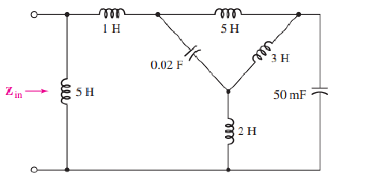
Determine the input impedance Zin of the one-port shown in Fig. 16.51 if ω is equal to (a) 50 rad/s; (b) 1000 rad/s.
(a)
The value of the input impedance for
Answer to Problem 23E
The value of the input impedance is
Explanation of Solution
Given data:
The value of
The given diagram is shown in Figure 1.
Calculation:
Let the inductances be
Let the capacitance
The expression for the inductive impedance
The expression for the capacitive impedance
Substitute
Substitute
Substitute
Substitute
The value of
Substitute
Substitute
Substitute
Substitute
Substitute
Substitute
Substitute
Substitute
The conversion of
Substitute
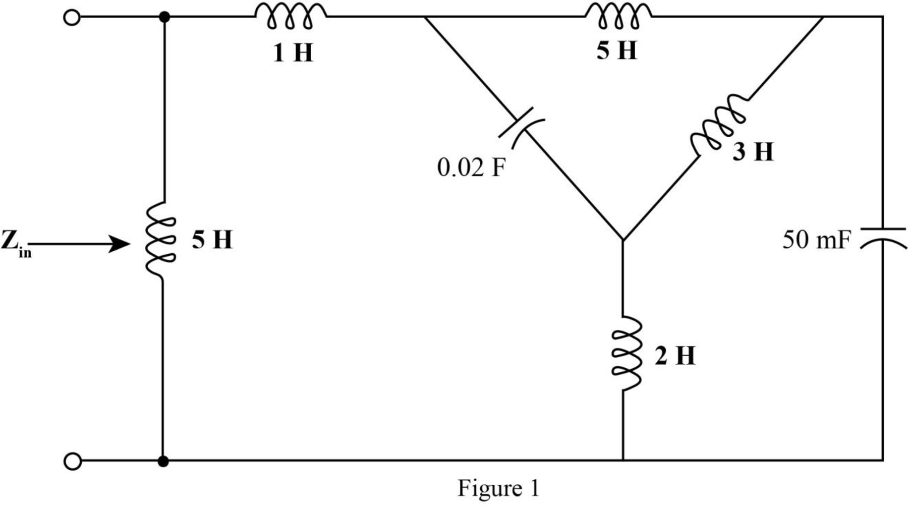
Mark the impedances and redraw the circuit.
The required diagram is shown in Figure 2
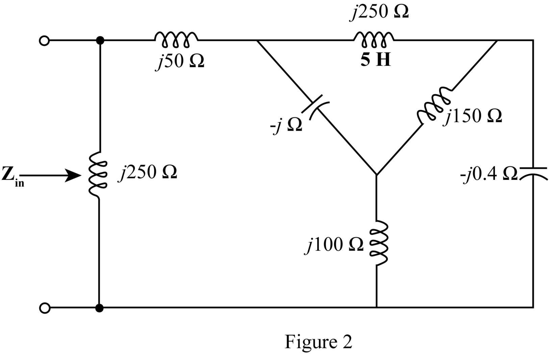
The
The required diagram is shown in the Figure 3.
Here,
The impedance
The impedance
The impedance
The required diagram is shown in Figure 4.
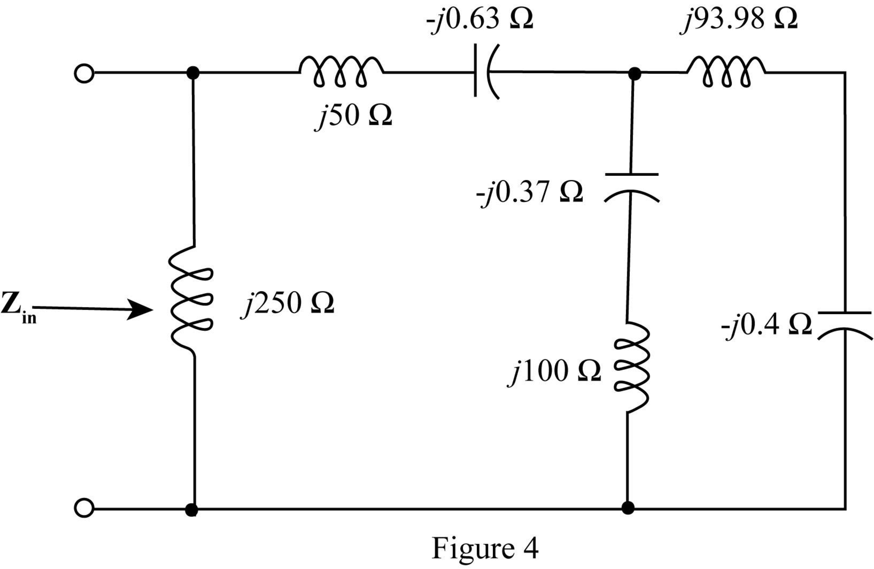
Add the impedances in series in the above network and redraw the network.
The required diagram is shown in Figure 5.
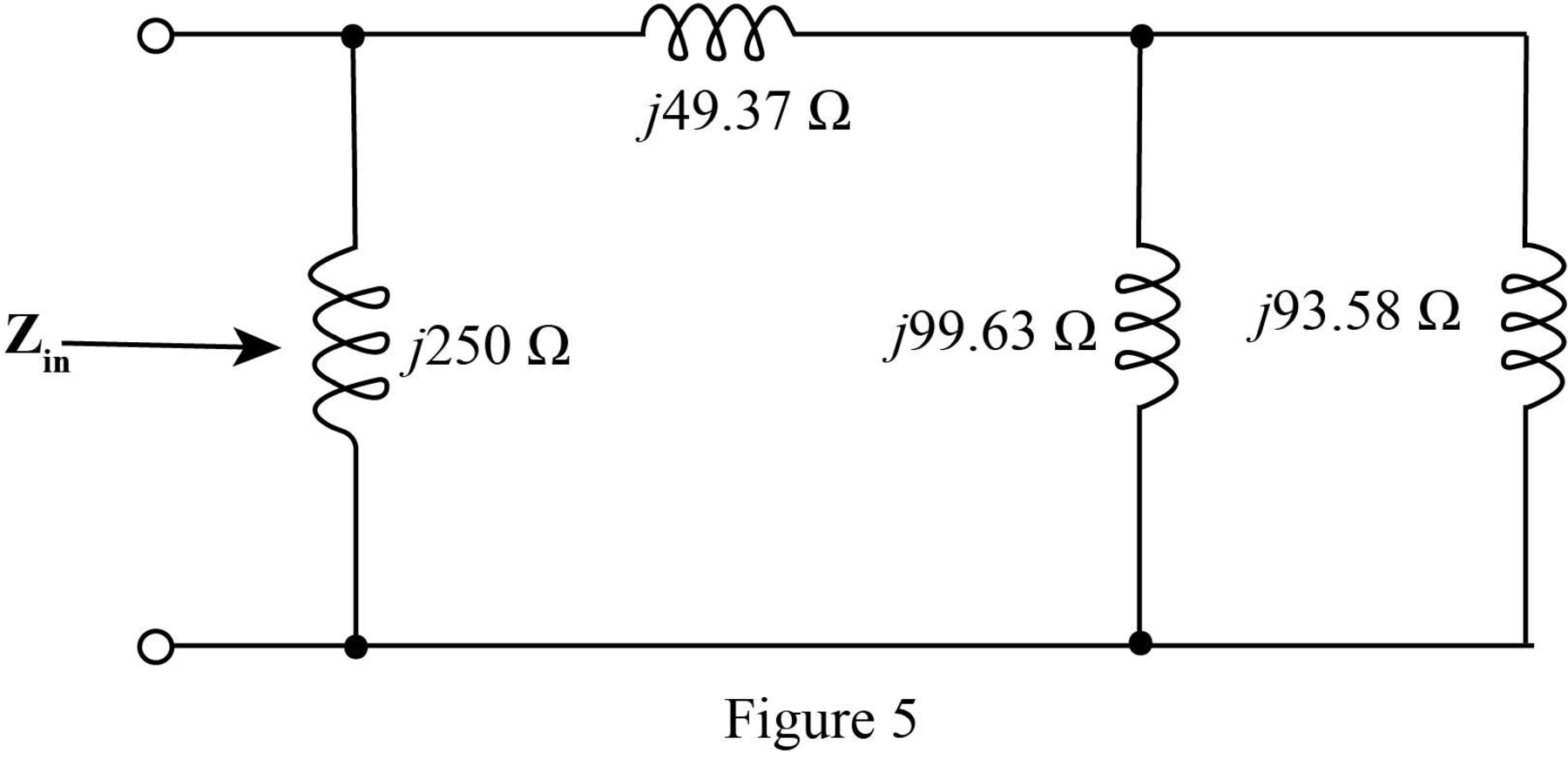
In the above circuit
Thus, the parallel combination
Mark the equivalent impedance and redraw the circuit.
The required figure is shown in Figure 6.
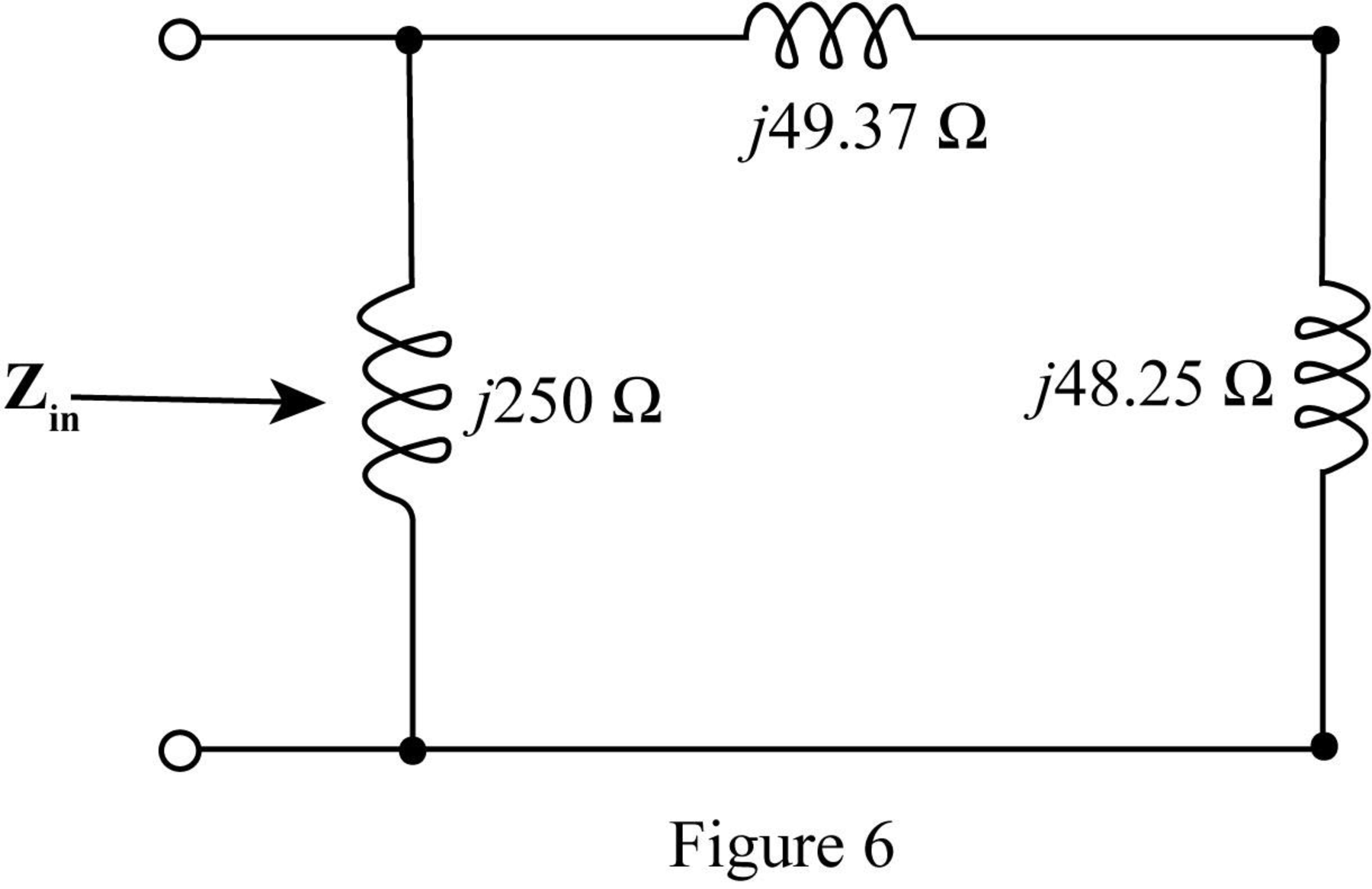
The value of the input impedance
Solve it further as,
Conclusion:
Therefore, the value of the input impedance for
(b)
The input impedance of the circuit is determined for
Answer to Problem 23E
The value of the input impedance for
Explanation of Solution
Given data:
The value of
Calculation:
Substitute
Substitute
Substitute
Substitute
Substitute
Substitute
Substitute
Mark the impedances and redraw the circuit.
The required diagram is shown in Figure 7
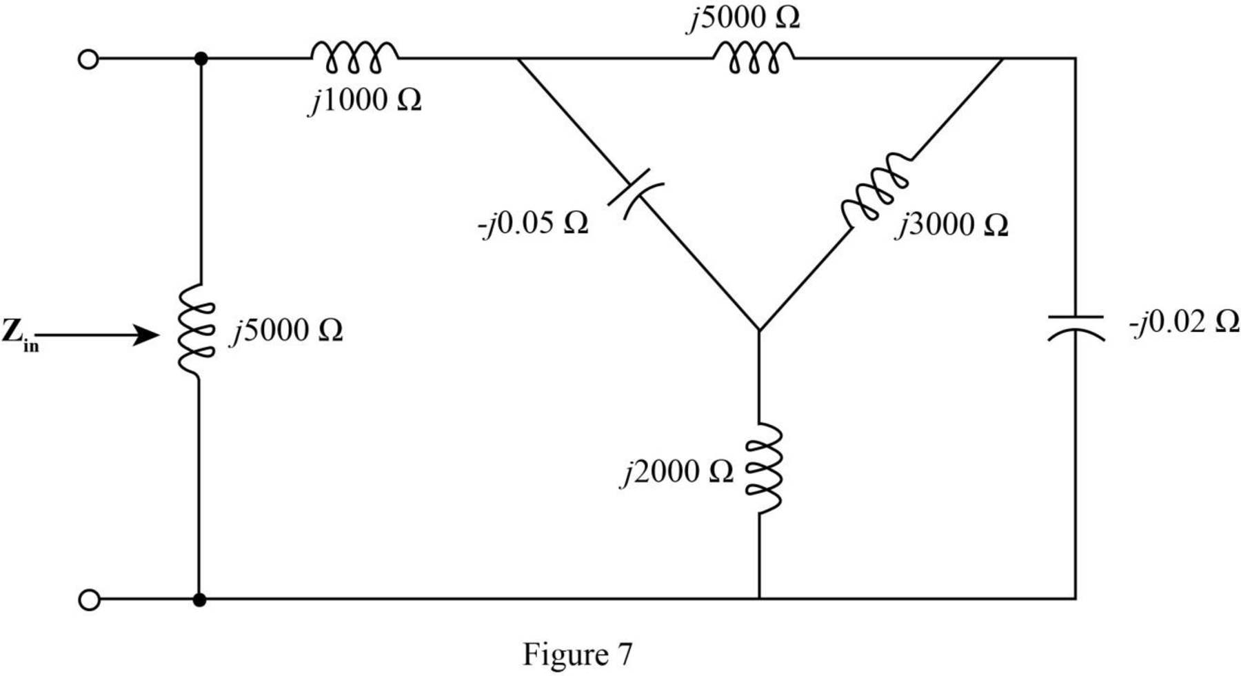
The
The required diagram is shown in the Figure 8
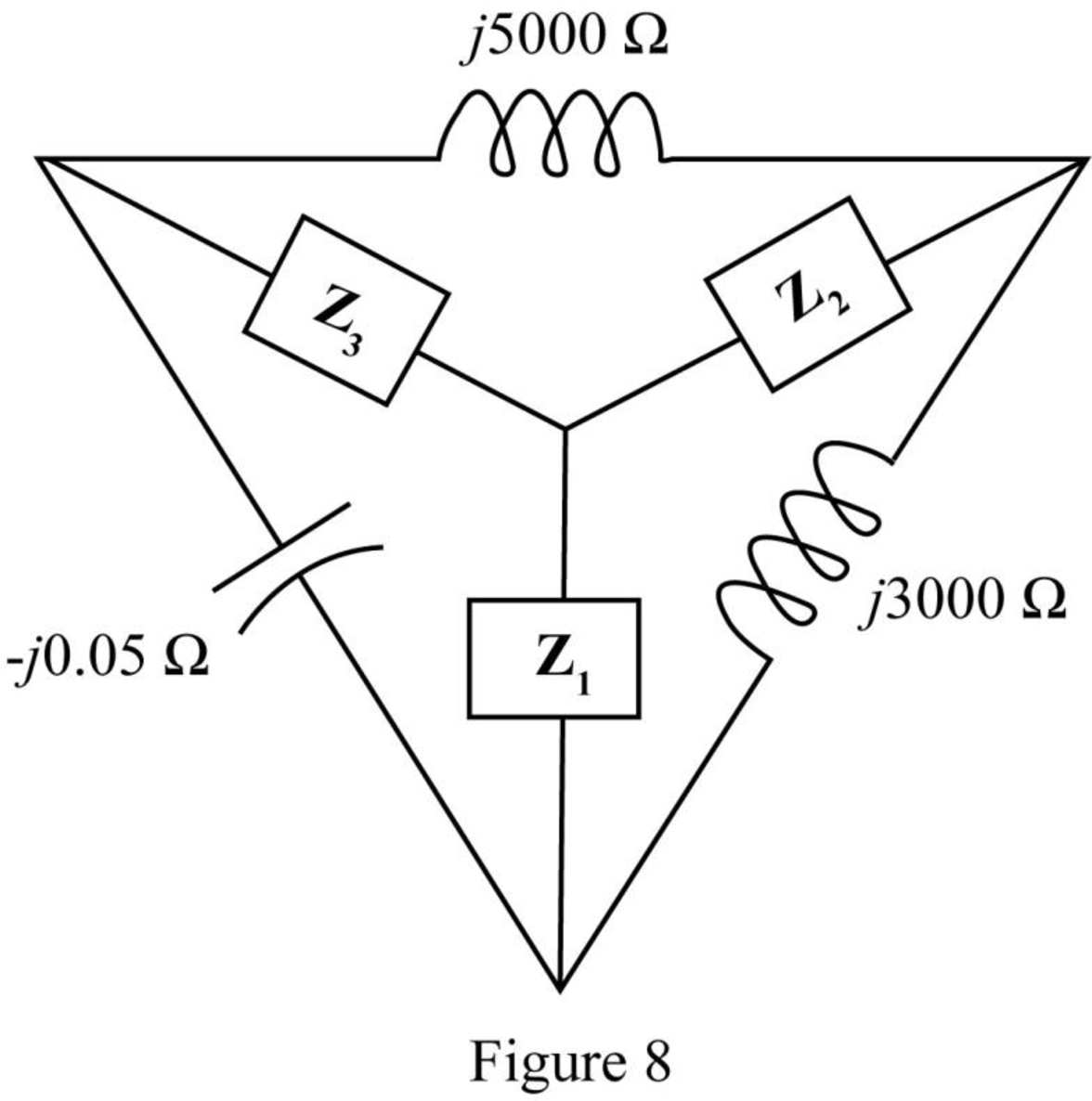
Here,
The impedance
The impedance
The impedance
The modified diagram is shown in Figure 9.
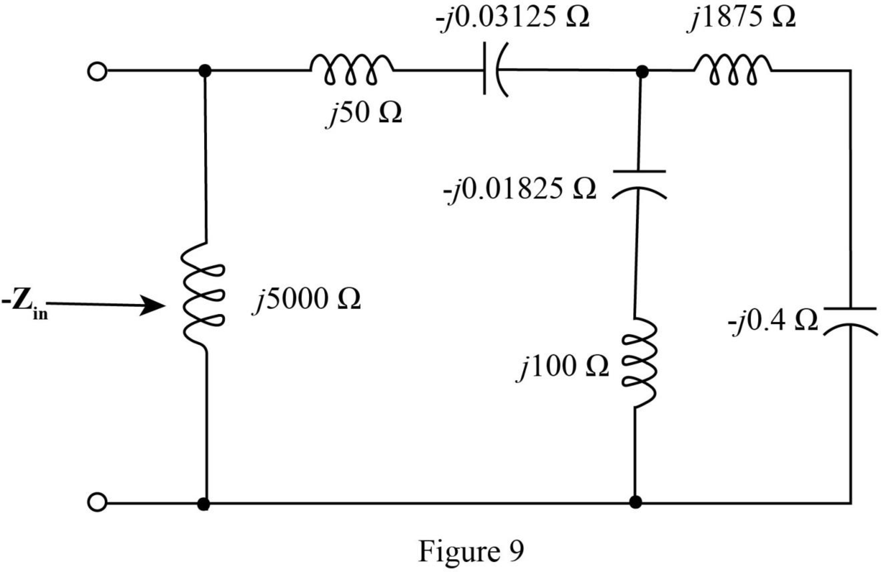
Add the impedances in series in the above network and redraw the network.
The required diagram is shown in Figure 10.
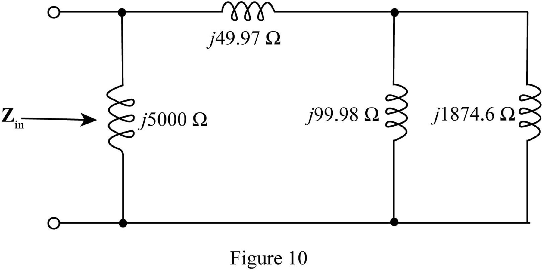
In the above circuit
Thus, the parallel combination
Mark the equivalent impedance and redraw the circuit.
The required figure is shown in Figure 11.
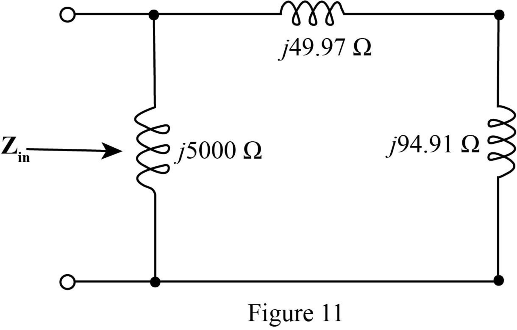
The value of the input impedance
Solve it further as,
Conclusion:
Therefore the value of the input impedance for
Want to see more full solutions like this?
Chapter 16 Solutions
Loose Leaf for Engineering Circuit Analysis Format: Loose-leaf
Additional Engineering Textbook Solutions
Fundamentals of Electric Circuits
Electric Circuits. (11th Edition)
Principles Of Electric Circuits
Electrical Engineering: Principles & Applications (7th Edition)
Electric machinery fundamentals
Fundamentals of Applied Electromagnetics (7th Edition)


- 3) Find Thevenin's equivalent between terminal a&b for the circuit shown in Fig. 4A 14 JL 4 r. 1A $15L 201 5 SU 6 Aarrow_forward16.20 a. Design a VCO as shown in Fig. 16.43(c) that has a nominal frequency of fo = 10 kHz. Assume Vcc = 15 V. D b. Calculate the modulation in the output frequencies if VCN is varied by ±10%. +Vcc R₂ VCN=Vcs+Ven Ven C3 R₂ C₂ 0.001 μF 5 R₁ NE/SE- 566 VCO C₁ 4 vo 1 www. 3—um Voarrow_forwardHome Work! SEATWORK 2 Show your complete solutions to the following problems and write it on a bond paper. Box your final answer. Scan your work and submit a pdf file using File Upload. For the two-port network shown 1H 1H 2F V, obtain the transfer function A. V2(s) / V1(s) B. V1(s) / 1(s)arrow_forward
- 16.32 Design a V/F converter as shown in Fig. 16.64 so that fo = 2.5 kHz at v₁ = 5 V. The input voltage v₁ can vary between 10 mV and 10 V. Assume VDD = - Vss = 5 V. Vss=-5 V ** +5 V R₂ -5 V R₂ C3 0.1 μF Rc H Rin www HHII Rhias www Cref Vref -5 V 1 2 3 4 5 6 7 9400 V/F Cint не 14 13 12 11 10 9 8 + VDD = +5 V NC R₁ C4 0.01 μF R₁ VO2 ƒ/2 Vol fo VDD = +5 Varrow_forwardPractice: || Find Io in the following circuit using the concept of source transformation, 16.7 Jjarrow_forwardPractic: Find Io in tfo]]owincirusg cocep! of source transformation. 16.7 2 Jj VWA T s .288 /99.46° A.arrow_forward
- Given the voltage and current shown in Fig. 16.70, find the parallel network internal to the container. That is, find the actual value of each component using the provided frequency.arrow_forwardDetermine the Y-parameters at a frequency of 10 kHz for the two-port network shown in figure below. Present your answer in matrix form. R1 5 Ohm 1 Ohm 400 μF R3 4 Ohm R2 200 μF R5 L5 mom. 5 Ohm 796 µF 6.4 mHarrow_forward16.13 Determine i,(t) in the circuit of Fig. 1 F 2 H ell 2Ω A e-2u(t) A 1Ωarrow_forward
- 16.29 Design the FSK modulator shown in Fig. 16.54(a) to produce frequencies of 1270 Hz and 1570 Hz corre- sponding to 1 (mark) and 0 (space), respectively. 1 1 Input digital data at 150 Hz VI Input digital serial data at 150 Hz RB 10 ΚΩ www Rc 50 ΚΩ Set at 39.24 ΚΩ FSK generator 1070-1270 Hz (a) AM/FM transmitter Q₁ 2N404 RA 50 ΚΩ Set at 41.51 ΚΩ RB 47 ΚΩ 0.01 μF HF 40 (b) Circuit 8 7 6 2 AM or FM transmitter Antenna Vcc = +5 V 4 NE/SE-555 3 C₁ 0.01 με 5 1070-1270 Hz Voarrow_forward5- The S-parameters of a two-port network are measured by means of a: A-Spectrum Analyzer B-RF Oscilloscope C-RF Signal Generator D-Vector Network Analyzerarrow_forwardConsider the digital circuit shown below - B. Y D Compute the value of Y if A=1, B=1, and C=1,arrow_forward
 Introductory Circuit Analysis (13th Edition)Electrical EngineeringISBN:9780133923605Author:Robert L. BoylestadPublisher:PEARSON
 Delmar's Standard Textbook Of ElectricityElectrical EngineeringISBN:9781337900348Author:Stephen L. HermanPublisher:Cengage Learning
 Programmable Logic ControllersElectrical EngineeringISBN:9780073373843Author:Frank D. PetruzellaPublisher:McGraw-Hill Education
 Fundamentals of Electric CircuitsElectrical EngineeringISBN:9780078028229Author:Charles K Alexander, Matthew SadikuPublisher:McGraw-Hill Education
 Electric Circuits. (11th Edition)Electrical EngineeringISBN:9780134746968Author:James W. Nilsson, Susan RiedelPublisher:PEARSON
 Engineering ElectromagneticsElectrical EngineeringISBN:9780078028151Author:Hayt, William H. (william Hart), Jr, BUCK, John A.Publisher:Mcgraw-hill Education,