College Physics
2nd Edition
ISBN: 9780134601823
Author: ETKINA, Eugenia, Planinšič, G. (gorazd), Van Heuvelen, Alan
Publisher: Pearson,
expand_more
expand_more
format_list_bulleted
Videos
Textbook Question
Chapter 19, Problem 11P
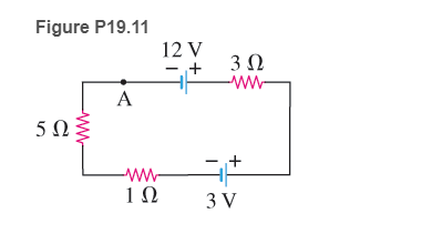
Sketch a potential-versus-location graph for the circuit shown in Figure P19.11. Start at A and move clockwise around the circuit.
Figure P19.11
Expert Solution & Answer
Want to see the full answer?
Check out a sample textbook solution
Chapter 19 Solutions
College Physics
Ch. 19 - Review Question 19.1 What condition(s) is/are...Ch. 19 - Review Question 19.2 Describe the changes in...Ch. 19 - Review Question 19.3 Explain the meaning of the...Ch. 19 - Review Question 19.4 Why does it make sense that...Ch. 19 - Review Question 19.5 What experimental evidence...Ch. 19 - Review Question 19.6 Eugenia says that the power...Ch. 19 - Review Question 19.7 Where is the electric...Ch. 19 - Review Question 19.8 Rank the four identical bulbs...Ch. 19 - Review Question 19.9 What does it mean when you...Ch. 19 - Review Question 19.10 Why does the resistance of a...
Ch. 19 - Two identical bulbs are connected on parallel...Ch. 19 - Compare the potential difference across bulbs 1...Ch. 19 - Two identical bulbs are in series as shown in...Ch. 19 - 4. Which statement below about the potential...Ch. 19 - Three circuits with identical bulbs and emf...Ch. 19 - 6. Rank in order the potential differences across...Ch. 19 - 7. Rank in order the five identical bulbs in the...Ch. 19 - Four identical bulbs are shown in the circuit in...Ch. 19 - Four identical bulbs are shown in the circuit in...Ch. 19 - Consider the circuit in Figure Q19.10. The switch...Ch. 19 - 11. Figure Q19.1 shows graphs for an incandescent...Ch. 19 - If an electric current were due to electrons...Ch. 19 - 13. Three light sources (a lightbulb, a blue LED ...Ch. 19 - What is the role of a battery in an electric...Ch. 19 - 16. Compare and contrast the physical quantities...Ch. 19 - Birds on high power lines Why can birds perch on a...Ch. 19 - 18. Preventing electric shock When a person is...Ch. 19 - (a) Using a voltmeter, how can you determine the...Ch. 19 - (a) What does it mean if the current through a...Ch. 19 - 21. Resistors become warm when there is an...Ch. 19 - At one time aluminum rather than copper wires were...Ch. 19 - 23. How do you connect an ammeter in a circuit to...Ch. 19 - Why do we connect electric devices in a home in...Ch. 19 - 26. Construct an electric circuit that is...Ch. 19 - 27. Most Christmas tree lights with incandescent...Ch. 19 - 28. Two students are arguing. Student A says that...Ch. 19 - Use the laws of energy and charge conservation to...Ch. 19 - When you close the switch in the circuit in Figure...Ch. 19 - 1. A bulb in a table lamp has a current of 0.50 A...Ch. 19 - A long wire is connected to the terminals of a...Ch. 19 - A typical flashlight battery will produce a 0.50-A...Ch. 19 - 4. * Four friends each have a battery, a bulb, and...Ch. 19 - 5. Draw a circuit that has a battery, a lightbulb,...Ch. 19 - Add another battery to the circuit described in...Ch. 19 - Add another lightbulb to the circuit with one...Ch. 19 - A 9.0-V battery is connected to a resistor so that...Ch. 19 - 10. * A graph of the electric potential versus...Ch. 19 - 11. Sketch a potential-versus-location graph for...Ch. 19 - 12. Bio Electric currents in the body A person...Ch. 19 - 13. An automobile lightbulb has a 1.0-A current...Ch. 19 - * If a long wire is connected to the terminals of...Ch. 19 - Determine the current through a 2.5- resistor when...Ch. 19 - 16. * You have a circuit with a 50-Ω, a 100- Ω,...Ch. 19 - You have a circuit with a 50-, a 100- , and a 150-...Ch. 19 - 18. * A toy has two red LEDs (), two green LEDs...Ch. 19 - * You want to power a green LED (VOpenG=2.1V) and...Ch. 19 - 20. * A circuit consists of a green LED and a ...Ch. 19 - 21. * You connect a 50-Ω resistor to a 9-V battery...Ch. 19 - 22. * EST Making tea You use an electric teapot to...Ch. 19 - * If a long wire is connected to the terminals of...Ch. 19 - ** Three friends are arguing with each other. Adam...Ch. 19 - 25. * You have a 40-W lightbulb and a 100-W bulb....Ch. 19 - * Does a 60-W lightbulb have more or less...Ch. 19 - 27. * (a) Write two loop rule equations and one...Ch. 19 - 28. * (a) Write Kirchhoff's loop rule for the...Ch. 19 - 29. * Repeat parts (a) and (b) of the previous...Ch. 19 - * (a) Determine the value of 1 so that there is a...Ch. 19 - 31. ** The current through resistor in Figure...Ch. 19 - andR3 shown in Figure P19.27 satisfy the relation...Ch. 19 - 33. * (a) Write the loop rule for two different...Ch. 19 - 34. ** Determine the value of , shown in Figure...Ch. 19 - * Determine (a) the equivalent resistance of...Ch. 19 - 36. (a) Determine the equivalent resistance of...Ch. 19 - 37. * Determine the equivalent resistance of the...Ch. 19 - * Determine (a) the equivalent resistance of the...Ch. 19 - You close the switch in the circuit in Figure...Ch. 19 - * You close the switch in the circuit in Figure...Ch. 19 - 42. * Home wiring A simplified electrical circuit...Ch. 19 - 43. ** (a) Write Kirchhoff's rules for two loops...Ch. 19 - of internal resistance. Because each row has the...Ch. 19 - 45. Home wiring A 120-V electrical line m a home...Ch. 19 - * Tree lights Nine tree lights are connected m...Ch. 19 - 47. * Two lightbulbs use 30 W and 60 W,...Ch. 19 - * Three identical resistors, when connected in...Ch. 19 - . (a) Determine the power delivered to a resistor...Ch. 19 - * Determine the equivalent resistance of the...Ch. 19 - 51 toI4 from largest to smallest Assume all wires...Ch. 19 - Figure P19.52 shows a real circuit that consists...Ch. 19 - * A 100-m-long copper wire of radius 0.12 mm and...Ch. 19 - 54. * BMT subway rail resistance The BMT subway...Ch. 19 - * Thermometer A platinum resistance thermometer...Ch. 19 - As the potential difference in volts across a thin...Ch. 19 - 57. * BIO Respiration detector A respiration...Ch. 19 - * A wire whose resistance is R is stretched so...Ch. 19 - 59. * Ratio reasoning Determine the ratio of the...Ch. 19 - ** Electronics detective You need to determine the...Ch. 19 - 61. * A battery produces a 2.0-A current when...Ch. 19 - 62. * Resistance of human nerve cell Some human...Ch. 19 - 63. * Conductive textiles Metal strands can be...Ch. 19 - 64. * EST Figure P19.64 shows an I-versus-V graph...Ch. 19 - * EST Figure P19.64 shows an I-versus- V graph for...Ch. 19 - *EST Figure P19.64 shows an I-versus- V graph for...Ch. 19 - * Wiring high-fidelity speakers Your high-fidelity...Ch. 19 - 68 * BIO EST Lifting forearm by electric current...Ch. 19 - 69. * EST Switches You have a power supply, a 10-W...Ch. 19 - ** Wiring a staircase Devise an electric circuit...Ch. 19 - 72. ** EST Electric water heater An electric hot...Ch. 19 - 73. ** BIO EST The hands and arms as a conductor...Ch. 19 - 75. * A nickel wire of length L and a voltmeter...Ch. 19 - ** Solve the previous problem if the internal...Ch. 19 - * EST Figure P19.77 shows an | I | -versus-V graph...Ch. 19 - VI a. Connect a voltmeter to a batterys terminals....Ch. 19 - equaled the number of electrons passing a cross...Ch. 19 - 80. * A 5.0-A current caused by moving electrons...Ch. 19 - 81. ** BIO Current across membrane wall of axon An...Ch. 19 - BIO Signals in nerve cells stimulate muscles The...Ch. 19 - BIO Signals in nerve cells stimulate muscles The...Ch. 19 - BIO Signals in nerve cells stimulate muscles The...Ch. 19 - BIO Signals in nerve cells stimulate muscles The...Ch. 19 - 86. The horizontal 4-Ω resistors in the two...Ch. 19 - 87. Suppose nerve impulses travel at 100 m/s in...Ch. 19 - BIO Effect of electric current on human body Nerve...Ch. 19 - BIO Effect of electric current on human body Nerve...Ch. 19 - BIO Effect of electric current on human body Nerve...Ch. 19 - BIO Effect of electric current on human body Nerve...Ch. 19 - BIO Effect of electric current on human body Nerve...Ch. 19 - BIO Effect of electric current on human body Nerve...Ch. 19 - BIO Effect of electric current on human body Nerve...
Additional Science Textbook Solutions
Find more solutions based on key concepts
16. A 200 g mass attached to a horizontal spring oscillates at a frequency of 2.0 Hz. At , the mass is at and ...
Physics for Scientists and Engineers: A Strategic Approach, Vol. 1 (Chs 1-21) (4th Edition)
(II) Derive the law of reflection—namely, that the angle of incidence equals the angle of reflection from a fla...
Physics for Scientists and Engineers with Modern Physics
31. Your forehead can withstand a force of about 6.0 kN before fracturing, while your cheekbone can withstand o...
Physics for Scientists and Engineers: A Strategic Approach with Modern Physics (4th Edition)
Jeannie Beanie mass 40kg, standing on a slippery ice, catches her dog Daisy mass 20kg, who leaps into her arms ...
Conceptual Integrated Science
25. If a machine multiplies force by a factor of 4, what other quantity is diminished, and by how much?
Conceptual Physical Science (6th Edition)
18.87 The rate of effusion—that is, leakage of a gas through tiny cracks—is proportional to vrms. If tiny crack...
University Physics (14th Edition)
Knowledge Booster


Learn more about
Need a deep-dive on the concept behind this application? Look no further. Learn more about this topic, physics and related others by exploring similar questions and additional content below.Similar questions
- A charge Q is placed on a capacitor of capacitance C. The capacitor is connected into the circuit shown in Figure P26.37, with an open switch, a resistor, and an initially uncharged capacitor of capacitance 3C. The switch is then closed, and the circuit comes to equilibrium. In terms of Q and C, find (a) the final potential difference between the plates of each capacitor, (b) the charge on each capacitor, and (c) the final energy stored in each capacitor. (d) Find the internal energy appearing in the resistor. Figure P26.37arrow_forwardConsider the circuit shown in Figure P26.24, where C1, = 6.00 F, C2 = 3.00 F. and V = 20.0 V. Capacitor C1 is first charged by closing switch S1. Switch S1 is then opened, and the charged capacitor is connected to the uncharged capacitor by closing Calculate (a) the initial charge acquired by C, and (b) the final charge on each capacitor.arrow_forward(a) Determine the equilibrium charge on the capacitor in the circuit of Figure P27.46 as a function of R. (b) Evaluate the charge when R = 10.0 . (c) Can the charge on the capacitor be zero? If so, for what value of R? (d) What is the maximum possible magnitude of the charge on the capacitor? For what value of R is it achieved? (c) Is it experimentally meaningful to take R = ? Explain your answer. If so, what charge magnitude does it imply? Figure P27.46arrow_forward
- Consider the circuit shown in Figure P20.52, where C1 = 6.00 F, C2 = 3.00 F, and V = 20.0 V. Capacitor C1 is first charged by closing switch S1. Switch S1 is then opened, and the charged capacitor is connected to the uncharged capacitor by closing S2. Calculate (a) the initial charge acquired by C1 and (b) the final charge on each capacitor. Figure P20.52arrow_forwardTwo capacitors, C1 = 25.0 F and C2 = 5.00 F, are connected in parallel and charged with a 100-V power supply. (a) Draw a circuit diagram and (b) calculate the total energy stored in the two capacitors. (c) What If? What potential difference would be required across the same two capacitors connected in series for the combination to store the same amount of energy as in part (b)? (d) Draw a circuit diagram of the circuit described in part (c).arrow_forwardThe circuit in Figure P27.85 shows four capacitors connected to a battery. The switch S is initially open, and all capacitors have reached their final charge. The capacitances are C1 = 6.00 F, C2 = 12.00 F, C3 = 8.00 F, and C4 = 4.00 F. a. Find the potential difference across each capacitor and the charge stored in each. b. The switch is now closed. What is the new final potential difference across each capacitor and the new charge stored in each? Figure P27.85arrow_forward
- A Pairs of parallel wires or coaxial cables are two conductors separated by an insulator, so they have a capacitance. For a given cable, the capacitance is independent of the length if the cable is very long. A typical circuit model of a cable is shown in Figure P27.87. It is called a lumped-parameter model and represents how a unit length of the cable behaves. Find the equivalent capacitance of a. one unit length (Fig. P27.87A), b. two unit lengths (Fig. P27.87B), and c. an infinite number of unit lengths (Fig. P27.87C). Hint: For the infinite number of units, adding one more unit at the beginning does not change the equivalent capacitance.arrow_forwardThe circuit shown in Figure P28.78 is set up in the laboratory to measure an unknown capacitance C in series with a resistance R = 10.0 M powered by a battery whose emf is 6.19 V. The data given in the table are the measured voltages across the capacitor as a function of lime, where t = 0 represents the instant at which the switch is thrown to position b. (a) Construct a graph of In (/v) versus I and perform a linear least-squares fit to the data, (b) From the slope of your graph, obtain a value for the time constant of the circuit and a value for the capacitance. v(V) t(s) In (/v) 6.19 0 5.56 4.87 4.93 11.1 4.34 19.4 3.72 30.8 3.09 46.6 2.47 67.3 1.83 102.2arrow_forwardConsider the combination of capacitors in Figure P16.42. (a) Find the equivalent single capacitance of the two capacitors in series and redraw the diagram (called diagram 1) with this equivalent capacitance. (b) In diagram 1, find the equivalent capacitance of the three capacitors in parallel and redraw the diagram as a single battery and single capacitor in a loop. (c) Compute the charge on the single equivalent capacitor. (d) Returning to diagram 1, compute the charge on each individual capacitor. Does the sum agree with the value found in part (c)? (e) What is the charge on the 24.0-F capacitor and on the 8.00-F capacitor? Compute the voltage drop across (f) the 24.0-F capacitor and (g) the 8.00-F capacitor. Figure P16.42arrow_forward
- Suppose you need to measure the potential difference between the points in Figure P29.4. Assume the voltmeter reading is the potential difference between the two leads: V = Vred Vblack. For each of the following measurements, determine at which point you would connect the red lead and at which point you would connect the black lead: a. Vb Va. b. Vc Vb. c. Vd Vc. d. Va Vd. FIGURE P29.4 Problems 4, 5, and 6.arrow_forwardFigure P18.26 shows a voltage divider, a circuit used to obtain a desired voltage Vout from a source voltage . Determine the required value of R2 if = 5.00 V, Vout = 1.50 V and R1 = 1.00 103 (Hint: Use Kirchhoff's loop rule, substituting Vout = IR2, to find the current. Then solve Ohms law for R2. Figure P18.26arrow_forward(a) What is the average power output of a heart defibrillator that dissipates 400 J of energy in 10.0 ms? (b) Considering the high-power output, why doesn’t the defibrillator produce serious bums?arrow_forward
arrow_back_ios
SEE MORE QUESTIONS
arrow_forward_ios
Recommended textbooks for you
 Physics for Scientists and Engineers with Modern ...PhysicsISBN:9781337553292Author:Raymond A. Serway, John W. JewettPublisher:Cengage Learning
 Physics for Scientists and EngineersPhysicsISBN:9781337553278Author:Raymond A. Serway, John W. JewettPublisher:Cengage Learning
 Principles of Physics: A Calculus-Based TextPhysicsISBN:9781133104261Author:Raymond A. Serway, John W. JewettPublisher:Cengage Learning
 Physics for Scientists and Engineers, Technology ...PhysicsISBN:9781305116399Author:Raymond A. Serway, John W. JewettPublisher:Cengage Learning
 College PhysicsPhysicsISBN:9781305952300Author:Raymond A. Serway, Chris VuillePublisher:Cengage Learning
Physics for Scientists and Engineers with Modern ...
Physics
ISBN:9781337553292
Author:Raymond A. Serway, John W. Jewett
Publisher:Cengage Learning
Physics for Scientists and Engineers
Physics
ISBN:9781337553278
Author:Raymond A. Serway, John W. Jewett
Publisher:Cengage Learning
Principles of Physics: A Calculus-Based Text
Physics
ISBN:9781133104261
Author:Raymond A. Serway, John W. Jewett
Publisher:Cengage Learning
Physics for Scientists and Engineers, Technology ...
Physics
ISBN:9781305116399
Author:Raymond A. Serway, John W. Jewett
Publisher:Cengage Learning
College Physics
Physics
ISBN:9781305952300
Author:Raymond A. Serway, Chris Vuille
Publisher:Cengage Learning
DC Series circuits explained - The basics working principle; Author: The Engineering Mindset;https://www.youtube.com/watch?v=VV6tZ3Aqfuc;License: Standard YouTube License, CC-BY