
Videos
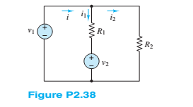
Refer to Figure P2.38, and assume
a. Thecurrents
b. The power delivered by the sources

Trending nowThis is a popular solution!

Chapter 2 Solutions
Principles and Applications of Electrical Engineering


- For the dc network in Figure Q1(b) calculate the unknown voltages V2 and V1 using Kirchoff's voltage law V2 + 2k 5V 2V 16V + Vi 2.2k Figure Q1(b)arrow_forwardQ1. For the circuit in the figure, using Kirchoff's rules, (a) Calculate the currents 1₁, 12 and 13 in the three branches. (b) What is the change in potential V₁ - V₁ =? 30 www 12 V 20 20 www 502 wi 30 13 V Barrow_forwardP2.70. Solve for the power delivered by the volt- age source in Figure P2.70, using the mesh- current method. 592 WWW M 792 i₁ 192 ww iz 1+ 62 V Figure P2.70 M 1192 iz •3Ωarrow_forward
- 4 decimals Four resistors, R1 = 100 ohms, R2 = 250 ohms, R3 = 350 ohms, and R4 = 200 ohms are connected such that the parallel combination of R1 and R2 is connected in series with the parallel combination of R3 and R4. The series-parallel combination is then connected across a 24-V DC power supply. Find the current through R4, in amperes.arrow_forwardUse the following constants if necessary. Coulomb constant, k = 8.987 x 10° N - m² /C2. Vacuum permitivity, co = 8.854 x 10 12 F/m. Magnetic Permeability of vacuum, Ho = 12.566370614356 x 10-' H/m. Magnitude of the Charge of one electron, e = -1.60217662 × 10⁻¹⁹ C. Mass of one electron, me = 9.10938356 x 10 31 kg. Unless specified otherwise, each symbol carries their usual meaning. For example, µC means micro coulomb. a R5 R3 e R9 R, R6 R8 Ry K Suppose you have the following circuit diagram. Here R1 =1.1 kN, R2 = 3.3 kN, R3 = 2.2 kN, R4 = 22 kN, R5 = 22 kN, Rg = 11 kN, R7 = 11 kN, Rg = 11 kN, R9 = 1.1 kN are the resistances on the circuit where kN stands for kilo ohm. The electromotive forces of the batteries are & = 5 volts and Ez = 3 volts. a) Calculate Rik. the resistance equivalent to R5, Re, R7, Rg and R9 between the terminals b and k. Value of Rhk Give your answer to at least two significance digits. Ω b) Calculate the current through R1.arrow_forwardWrite the equations for the network shown in Figure 2.23 and put them into standard form. Find the value for V₁ and V2. (V3 at node 3 is 10V) 1A VI Node 3 W 202 502 www w 1052 10 V 1/2 M50arrow_forward
- Consider the circuit shown in the figure below. (Let R₁ = 6.00 0, R₂ = 8.00 0, and 8 - 10.0 V.) 2.000 W 10.00 www 5.000 www & 16 (a) Find the voltage across R₁. (b) Find the current in R₁. R₂ wwwarrow_forwardanswer as soon C) Figure Q2(c) shows a simple electronic circuit. A recently graduated engineering student from eau has been tasked by his Senior Engineer to determine the equivalent circuit between Terminal A and B. Please help him to analyze and find the equivalent resistance using delta-wye transformationarrow_forward4 decimals Four resistors, R1 = 100 ohms, R2 = 250 ohms, R3 = 350 ohms, and R4 = 200 ohms are connected such that the parallel combination of R1 and R2 is connected in series with the parallel combination of R3 and R4. The series-parallel combination is then connected across a 24-V DC power supply. Find the total current of the circuit, in amperes.arrow_forward
- Refer to the figure. Given 2RR R2 = 3R2 - RL a) Design the power supply circuit so that y = 3v,when R,-600 Q. by Assume input voltage is 180 V. Which resistor in the circuit dissipates the most power? What is the power? c) Which resistor dissipates the least power? What is the power? R2 ww R ww I RL 14. ww- 年 wwarrow_forwardDifferentiate between Kirchhoff's Voltage Law and Kirchhoff's Current Law. Support you answer by appropriate example. Debate that how these laws are supportive to solve complex circuits.arrow_forwardFor the circuit shown in Figure Q2.1, use the Superposition Theorem, to calculate: The current flowing through the resistor R1 The power consumed by R1 The voltage dropped by R1 Use Kirchhoff's Current Law (or otherwise) to calculate the current flowing through resistor R2 R1 3k2 V1 -5V R2 2kQ 11 20mA Figure Q2.1 An alternating current waveform is given by I(t)=15 sin (50n t + 1/2). Find the following: Peak current value, RMS value of the current, and Peak-to-peak current value Frequency in Hertz, and initial phase angle.arrow_forward
 Introductory Circuit Analysis (13th Edition)Electrical EngineeringISBN:9780133923605Author:Robert L. BoylestadPublisher:PEARSON
 Delmar's Standard Textbook Of ElectricityElectrical EngineeringISBN:9781337900348Author:Stephen L. HermanPublisher:Cengage Learning
 Programmable Logic ControllersElectrical EngineeringISBN:9780073373843Author:Frank D. PetruzellaPublisher:McGraw-Hill Education
 Fundamentals of Electric CircuitsElectrical EngineeringISBN:9780078028229Author:Charles K Alexander, Matthew SadikuPublisher:McGraw-Hill Education
 Electric Circuits. (11th Edition)Electrical EngineeringISBN:9780134746968Author:James W. Nilsson, Susan RiedelPublisher:PEARSON
 Engineering ElectromagneticsElectrical EngineeringISBN:9780078028151Author:Hayt, William H. (william Hart), Jr, BUCK, John A.Publisher:Mcgraw-hill Education,