
Power System Analysis and Design (MindTap Course List)
6th Edition
ISBN: 9781305632134
Author: J. Duncan Glover, Thomas Overbye, Mulukutla S. Sarma
Publisher: Cengage Learning
expand_more
expand_more
format_list_bulleted
Concept explainers
Videos
Textbook Question
Chapter 2, Problem 2.50P
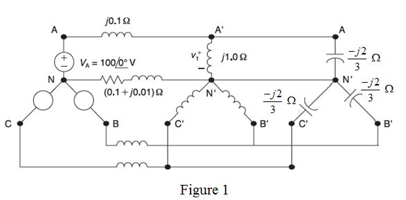
Consider the balanced three-phase system shown in Figure 2.34. Deter mine
Expert Solution & Answer

Trending nowThis is a popular solution!

Students have asked these similar questions
A balanced delta connected load of 15 + J18 Q per phase is connected at
the end of a three-phase line as shown in Figure 2.25. The line impedance
is 14-j2 Q per phase. The line is supplied from a three-phase source with
a line-to-line voltage of 207.85 V rms. Taking Van as reference, determine
the following: (a) Current in phase a. (b) Total complex power supplied
from the source. (c) Magnitude of the line-to-line voltage at the load
terminal.
1+j2N
wwwm
VL = 207.85 V
bo
Co-
FIGURE 2.25
Circuit for Problem 2.13.
b
a
15+j18 N
Differentiate Wye and Delta Connection in Three Phase System and Relate it with Computer Engineering
The section bus-bars A and B are linked by a bus-bar reactor rated at 6000 kVA with 12% reactance. On bus-bar-A, there are two generators each of 10 MVA with 8% reactance and on bus-bar-B, two generators each of 6000 kVA with 10% reactance.
Find the steady MVA fed into a dead short circuit all phases on B with bus-bar reactor in the circuit.
Chapter 2 Solutions
Power System Analysis and Design (MindTap Course List)
Ch. 2 - The rms value of v(t)=Vmaxcos(t+) is given by a....Ch. 2 - If the rms phasor of a voltage is given by V=12060...Ch. 2 - If a phasor representation of a current is given...Ch. 2 - Prob. 2.4MCQCh. 2 - Prob. 2.5MCQCh. 2 - Prob. 2.6MCQCh. 2 - Prob. 2.7MCQCh. 2 - Prob. 2.8MCQCh. 2 - Prob. 2.9MCQCh. 2 - The average value of a double-frequency sinusoid,...
Ch. 2 - The power factor for an inductive circuit (R-L...Ch. 2 - The power factor for a capacitive circuit (R-C...Ch. 2 - Prob. 2.13MCQCh. 2 - The instantaneous power absorbed by the load in a...Ch. 2 - Prob. 2.15MCQCh. 2 - With generator conyention, where the current...Ch. 2 - Consider the load convention that is used for the...Ch. 2 - Prob. 2.18MCQCh. 2 - The admittance of the impedance j12 is given by...Ch. 2 - Consider Figure 2.9 of the text, Let the nodal...Ch. 2 - The three-phase source line-to-neutral voltages...Ch. 2 - In a balanced three-phase Y-connected system with...Ch. 2 - In a balanced system, the phasor sum of the...Ch. 2 - Consider a three-phase Y-connected source feeding...Ch. 2 - For a balanced- load supplied by a balanced...Ch. 2 - A balanced -load can be converted to an...Ch. 2 - When working with balanced three-phase circuits,...Ch. 2 - The total instantaneous power delivered by a...Ch. 2 - The total instantaneous power absorbed by a...Ch. 2 - Under balanced operating conditions, consider the...Ch. 2 - One advantage of balanced three-phase systems over...Ch. 2 - While the instantaneous electric power delivered...Ch. 2 - Given the complex numbers A1=630 and A2=4+j5, (a)...Ch. 2 - Convert the following instantaneous currents to...Ch. 2 - The instantaneous voltage across a circuit element...Ch. 2 - For the single-phase circuit shown in Figure...Ch. 2 - A 60Hz, single-phase source with V=27730 volts is...Ch. 2 - (a) Transform v(t)=75cos(377t15) to phasor form....Ch. 2 - Let a 100V sinusoidal source be connected to a...Ch. 2 - Consider the circuit shown in Figure 2.23 in time...Ch. 2 - For the circuit shown in Figure 2.24, compute the...Ch. 2 - For the circuit element of Problem 2.3, calculate...Ch. 2 - Prob. 2.11PCh. 2 - The voltage v(t)=359.3cos(t)volts is applied to a...Ch. 2 - Prob. 2.13PCh. 2 - A single-phase source is applied to a...Ch. 2 - Let a voltage source v(t)=4cos(t+60) be connected...Ch. 2 - A single-phase, 120V(rms),60Hz source supplies...Ch. 2 - Consider a load impedance of Z=jwL connected to a...Ch. 2 - Let a series RLC network be connected to a source...Ch. 2 - Consider a single-phase load with an applied...Ch. 2 - A circuit consists of two impedances, Z1=2030 and...Ch. 2 - An industrial plant consisting primarily of...Ch. 2 - The real power delivered by a source to two...Ch. 2 - A single-phase source has a terminal voltage...Ch. 2 - A source supplies power to the following three...Ch. 2 - Consider the series RLC circuit of Problem 2.7 and...Ch. 2 - A small manufacturing plant is located 2 km down a...Ch. 2 - An industrial load consisting of a bank of...Ch. 2 - Three loads are connected in parallel across a...Ch. 2 - Prob. 2.29PCh. 2 - Figure 2.26 shows three loads connected in...Ch. 2 - Consider two interconnected voltage sources...Ch. 2 - Prob. 2.35PCh. 2 - Prob. 2.36PCh. 2 - Prob. 2.37PCh. 2 - Prob. 2.38PCh. 2 - Prob. 2.39PCh. 2 - A balanced three-phase 240-V source supplies a...Ch. 2 - Prob. 2.41PCh. 2 - A balanced -connected impedance load with (12+j9)...Ch. 2 - A three-phase line, which has an impedance of...Ch. 2 - Two balanced three-phase loads that are connected...Ch. 2 - Two balanced Y-connected loads, one drawing 10 kW...Ch. 2 - Three identical impedances Z=3030 are connected in...Ch. 2 - Two three-phase generators supply a three-phase...Ch. 2 - Prob. 2.48PCh. 2 - Figure 2.33 gives the general -Y transformation....Ch. 2 - Consider the balanced three-phase system shown in...Ch. 2 - A three-phase line with an impedance of...Ch. 2 - A balanced three-phase load is connected to a...Ch. 2 - What is a microgrid?Ch. 2 - What are the benefits of microgrids?Ch. 2 - Prob. CCSQCh. 2 - Prob. DCSQ
Knowledge Booster


Learn more about
Need a deep-dive on the concept behind this application? Look no further. Learn more about this topic, electrical-engineering and related others by exploring similar questions and additional content below.Similar questions
- Q2) A 13.2-kV single-phase generator supplies power to a load through a transmission line. The load's impedance is Ztoad 500 236.87° ohm , and the transmission line's impedance is Zine = 60 253.1° ohm. To reduce transmission line losses to 0.0103 of its losses without using the transformers design and use two transformers T1 between the generator and the transmission line and T2 between the transmission line and the load.arrow_forwardQ2) A 13.2-kV single-phase generator supplies power to a load through a transmission line. The load's impedance is Zload = 500 236.87° ohm, and the transmission line's impedance is Zline = 60 253.1° ohm. To reduce transmission line losses to 0.0103 of its losses without using the transformers design and use two transformers T1 between the generator and the transmission line and T2 between the transmission line and the load.arrow_forwardProblem 1 - Series en Parallel AC networks [19] Look at the circuit in Figure 1 and determine the following: (a) Total Admittance. (b) Total Impedance. (c) Total Current (l:). (d) Current (I1) through impedance Z2. (e) Current (12) through impedance Z3. (f) Current (I3) through impedance Z4. (g) Is this an inductive or capacitive circuit? A. B Zs 220V;50HZ Figure 1 (h) Voltage across Z1. (i) Voltage across A and B. G) Voltage across Zs. Z1 = 3 + j5 ohm Z2 = 10 + jo ohm Z3 = 5 + j15 ohm Z4 = 10 – j30 ohm Zs = 20 – j30 ohm Admittance and Impedance in rectangular notation. All currents and voltage in polar notation. Take voltage as reference.arrow_forward
- Q2 (a) Three-phase generator consist of three set of single-phase generators, with voltages equal in magnitude but differing in phase angle by 120° apart. (i) Sketch phasor diagram of the three-phase voltages VA, VB and Vc (ii) Plot the three-phase voltages waveform in Q2(a)(i) in single plot.arrow_forward(b) A symmetrical delta-connected 415V three-phase supply is feed to an asymmetrical delta- connected load as shown in Figure Q2(b). Assume that it is a RYB sequence. The impedances of the load are ZrY = 50 + j50 N , ZYB = 150 + j0 N and ZBr = 50 –j50 N. jos (i) Determine and draw the phasor diagram of phase currents in the load. (ii) Determine and draw the phasor diagram of line currents in the system.arrow_forward(b) A symmetrical delta-connected 415V three-phase supply is feed to an asymmetrical delta- connected load as shown in Figure Q2(b). Assume that it is a RYB sequence. The impedances of the load are ZRY = 50 +j50 Q , ZYB = 150 + j0 Q and ZBR= 50 – j50 N. (i) Determine and draw the phasor diagram of phase currents in the load. (ii) Determine and draw the phasor diagram of line currents in the system.arrow_forward
- 2) The one-line diagram of a three-phase power system is as shown in Figure. Impedance are marked in per-unit on a 100-MVA, 400-kV base. The load at bus 2 is S2=15.93 MW - j33.4 Mvar, and at bus 3 is S3-77 MW + j14 Mvar. It is required to hold the voltage at bus 3 at ...L0 kV. Working in per-unit, determine the voltage at buses 2 and 1. (Please determine the voltage magnitude within the specified limits: 410-450 V. By considering the voltage magnitude value you determined yourself, solve the question.) V₁ j0.5 pu V₂ j0.4 pu S₂ Figure V3 S3arrow_forwardQ4/For the three-phase power network shown in Figure. the various components are: GI: 100 MVA, 0.30 pu reactance. G2: 60 MVA, 0.18 pu reactance. Transformers (cach): 50 MVA, 0.10 pu reactance. Inductive reactor X: 0.20 pu on a base of 100 MVA. Lines (each): 80 ohms (reactive); neglect resistance. with the network initially unloaded and a line voltage of 110 kV, a symmetrical short circuit occurs at midpoint E of line 2. Calculate the short circuit MVA to be interrupted by the circuit breakers A and B at the ends of the line. T3 38 L1 L2 G2 Bas 12 T4 Busarrow_forwardA balanced A-connected load consisting of a pure resistances of 18 Q per phase is in parallel with a purely resistive balanced Y-connected load of 12 Q per phase as shown in Figure 2.26. The combination is connected to a threephase balanced supply of 346.41-V rms (line-to-line) via a three- phase line having an inductive reactance of j3 Q per phase. Taking the phase voltage Van as reference, determine (a) The current, real power, and reactive power drawn from the supply. (b) The line-to-neutral and the line-to-line voltage of phase a at the combined load terminals. j3N |VL| = 346.41 V be FIGURE 2.26 Circuit for Problem 2.16. b {12Ω n a {18 Ωarrow_forward
- A three-phase balanced load of 15A per phase is supplied by a steel wire armoured cable with a c.s.a. of 2.5mm². The voltage drop for this cable is 15mv/A/m and the circuit is 40m long. Calculate the voltage drop in the cable.arrow_forward6.5% ans ex A so kvA. 2o00/20 V, So He single-phase transformar has impedance drof of8% and resistance drop of 4%. Caleulate. The Requlation of the Thams former at full- Load o8 P.s Legging. also find The Power factor at which Voltage requlation will Be Zero. Sols 0.5 leading. s alculate The % Noltege Requlation af atransformar in w hich the Percantage resistance drof is 1% and Percentage dre is 6% when The Power fador is 0.8 lagging ) > unity aMS 38 % ans 1 % (シ→ 0.8 leading . amS - 2.2%arrow_forwardIn the system shown in Figure 1, the transformers are connected star-star with both star points grounded and the generators are connected in star with thier star points grounded. The system base is 15 MVA. The transformers all have reactances of 0.04 p.u. on this 15 MVA base. The reactances of all other elements are given in Table 1 (in 2) and the voltage levels are given in Table 2. p.u. G1 p.u. T1 jö Per-Unit Convert all values to p.u. on a 15 MVA base. Xa= p.u. Xc₂= XL = V BABE G1 2 X 9 T3 Figure 1: A section of the distribution system T1 L Table 1: Sequence reactances (2) 3 G1 L G2 0.3 0.59 0.01 4 L 9/10 10 Fault Voltage What is the voltage at bus 3 (in Volts) after the fault has occurred? Vp= V T2 5 T2 34 10/4 Table 2: Voltage bases (kV) G2 4 T3 10/9 | G2 Fault Current A three-phase fault with a fault reactance of 0.01 p.u. occurs at bus 3. Calculate the fault current flowing at the fault point in KA. Ip=-j KA Soarrow_forward
arrow_back_ios
SEE MORE QUESTIONS
arrow_forward_ios
Recommended textbooks for you
 Power System Analysis and Design (MindTap Course ...Electrical EngineeringISBN:9781305632134Author:J. Duncan Glover, Thomas Overbye, Mulukutla S. SarmaPublisher:Cengage Learning
Power System Analysis and Design (MindTap Course ...
Electrical Engineering
ISBN:9781305632134
Author:J. Duncan Glover, Thomas Overbye, Mulukutla S. Sarma
Publisher:Cengage Learning
Fault Analysis in Power Systems part 1a; Author: GeneralPAC: Power System Tutorials;https://www.youtube.com/watch?v=g8itg4MOjok;License: Standard youtube license