Videos
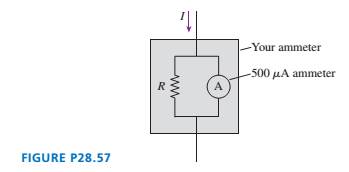
A circuit you’re building needs an ammeter that goes from 0 mA to a full-scale reading of 50 mA. Unfortunately, the only ammeter in the storeroom goes from
a. What value of R must you use so that the meter will go to full scale when the current I is 50 mA?
b. What is the effective resistance of your ammeter?
Want to see the full answer?
Check out a sample textbook solution
Chapter 28 Solutions
Physics for Scientists and Engineers: A Strategic Approach, Vol. 1 (Chs 1-21) (4th Edition)


- A lightbulb is connected to a variable power supply. As the potential across the bulb is varied, the resulting current and the filaments temperature are measured. The data are listed in Table P28.38. a. Find R for each entry in Table P28.38, and then plot R as a function of T. b. Assume that room temperature is at 293 K. Find R0 (resistance at room temperature). Comment on your result.arrow_forwardFigure P29.77 shows a circuit with two batteries and three resistors. a. How much current flows through the 2.00- resistor? b. What is the potential difference between points a and b in the circuit?arrow_forwardFigure P29.45 shows five resistors connected between terminals a and b. a. What is the equivalent resistance of this combination of resistors? b. What is the current through each resistor if a 24.0-V battery is connected across the terminals?arrow_forward
- What is the equivalent resistance between points a and b of the six resistors shown in Figure P29.70? FIGURE P29.70arrow_forwardIn Figure P29.81, N real batteries, each with an emf and internal resistance r, are connected in a closed ring. A resistor R can be connected across any two points of this ring, causing there to be n real batteries in one branch and N n resistors in the other branch. Find an expression for the current through the resistor R in this case.arrow_forwardA battery is used to charge a capacitor through a resistor as shown in Figure P27.44. Show that half the energy supplied by the battery appears as internal energy in the resistor and half is stored in the capacitor. Figure P27.44arrow_forward
- The circuit shown in Figure P28.78 is set up in the laboratory to measure an unknown capacitance C in series with a resistance R = 10.0 M powered by a battery whose emf is 6.19 V. The data given in the table are the measured voltages across the capacitor as a function of lime, where t = 0 represents the instant at which the switch is thrown to position b. (a) Construct a graph of In (/v) versus I and perform a linear least-squares fit to the data, (b) From the slope of your graph, obtain a value for the time constant of the circuit and a value for the capacitance. v(V) t(s) In (/v) 6.19 0 5.56 4.87 4.93 11.1 4.34 19.4 3.72 30.8 3.09 46.6 2.47 67.3 1.83 102.2arrow_forwardA student makes a homemade resistor from a graphite pencil 5.00 cm long, where the graphite is 0.05 mm indiameter. The resistivity of the graphite is =1.38102/m . The homemade resistor is place inseries with a switch, a 10.00-mF capacitor and a 0.50-V power source, (a) What is the BC time constant of the circuit? (b) What is the potential drop across the pencil 1.00 s after the switch is closed?arrow_forwardFour resistors are connected to a battery as shown in Figure P21.40. The current in the battery is I, the battery emf is , and the resistor values are R1 = R, R2 = 2R, R3 = 4R, and R4 = 3R. (a) Rank the resistors according to the potential difference across them, from largest to smallest. Note any cases of equal potential differences. (b) Determine the potential difference across each resistor in terms of . (c) Rank the resistors according to the current in them, from largest to smallest. Note any cases of equal currents. (d) Determine the current in each resistor in terms of I. (e) If R3 is increased, what happens to the current in each of the resistors? (f) In the limit that R3 , what are the new values of the current in each resistor in terms of I, the original current in the battery? Figure P21.40arrow_forward
- In the circuit of Figure P27.20, the current I1 = 3.00 A and the values of for the ideal battery and R are unknown. What are the currents (a) I2 and (b) I3? (c) Can you find the values of and R? If so, find their values. If not, explain. Figure P27.20arrow_forwardConsider the circuit shown in Figure P28.9. (R = 22.0 N.) 10.0 2 25.0 V 10.0 2 5.00 2 5.00 2 Figure P28.9 (a) Find the current in the 22.0 N resistor. A (b) Find the potential difference between points a and b.arrow_forwardIn Figure P28.67, suppose the switch has been closed for a length of time sufficiently long for the capacitor to become fully charged. (E = 8.50 V, r1 = 10 kN, and r2 = 16 kN.) 10.0 µF 3.00 k2 Figure P28.67 (a) Find the steady-state current in each resistor. I = 327 HA I2 = 327 HA 13-kn = 0 HA (b) Find the charge Q on the capacitor. 52 (c) The switch is opened at t = 0. Write an equation for the current IR, in R2 as a function of time. O (327 HA)e-t/(0.190 s) O (275 µA)et/(0.190 s) O (275 µA)e-t/(0.190 s) O (327 µA)et/(0.190 s) (d) Find the time that it takes for the charge on the capacitor to fall to one-fifth its initial value. msarrow_forward
 Physics for Scientists and Engineers: Foundations...PhysicsISBN:9781133939146Author:Katz, Debora M.Publisher:Cengage Learning
 Principles of Physics: A Calculus-Based TextPhysicsISBN:9781133104261Author:Raymond A. Serway, John W. JewettPublisher:Cengage Learning
 Physics for Scientists and Engineers, Technology ...PhysicsISBN:9781305116399Author:Raymond A. Serway, John W. JewettPublisher:Cengage Learning
 Physics for Scientists and EngineersPhysicsISBN:9781337553278Author:Raymond A. Serway, John W. JewettPublisher:Cengage Learning
 Physics for Scientists and Engineers with Modern ...PhysicsISBN:9781337553292Author:Raymond A. Serway, John W. JewettPublisher:Cengage Learning