
Concept explainers
Videos
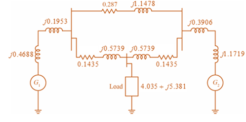
Consider the single-Line diagram of a power system shown in Figure 3.42 with equipment ratings given:
Generator
Generator
Three-phase
Three-phase
Load:
Choose a base of 100 MVA for the system and 132-kV base in the transmission-line circuit. Let the load be modeled as a parallel combination of resistance and inductance. Neglect transformer phase shifts. Draw a per-phase equivalent circuit of the system showing all impedances in per unit.

Trending nowThis is a popular solution!

Chapter 3 Solutions
Power System Analysis and Design (MindTap Course List)


- Consider the oneline diagram shown in Figure 3.40. The three-phase transformer bank is made up of three identical single-phase transformers, each specified by X1=0.24 (on the low-voltage side), negligible resistance and magnetizing current, and turns ratio =N2/N1=10. The transformer bank is delivering 100 MW at 0.8 p.f. lagging to a substation bus whose voltage is 230 kV. (a) Determine the primary current magnitude, primary voltage (line-to-line) magnitude, and the three-phase complex power supplied by the generator. Choose the line-to-neutral voltage at the bus, Va as the reference Account for the phase shift, and assume positive-sequence operation. (b) Find the phase shift between the primary and secondary voltages.arrow_forwardConsider three ideal single-phase transformers (with a voltage gain of ) put together as three-phase bank as shown in Figure 3.35. Assuming positive-sequence voltages for Va,Vb, and Vc find Va,Vb, and VC. in terms of Va,Vb, and Vc, respectively. (a) Would such relationships hold for the line voltages as well? (b) Looking into the current relationships, express IaIb and Ic in terms of IaIb and Ic respectively. (C) Let S and S be the per-phase complex power output and input. respectively. Find S in terms of S.arrow_forwardThe per-unit equivalent circuit of two transformers Ta and Tb connected in parallel, with the same nominal voltage ratio and the same reactan of 0.1 per unit on the same base, is shown in Figure 3.43. Transformer Tb has a voltage-magnitude step-up toward the load of 1.05 times that of Ta (that is, the tap on the secondary winding of Tb is set to 1.05). The load is represented by 0.8+j0.6 per unit at a voltage V2=1.0/0 per unit. Determine the complex power in per unit transmitted to the load through each transformer, comment on how the transformers share the real and reactive powers.arrow_forward
- A bank of three single-phase transformers, each rated 30MVA,38.1/3.81kV, are connected in Y- with a balanced load of three 1, Y-connected resistors. Choosing a base of 90MVA,66kV for the high-voltage side of the three-phase transformer. spify the base for the low-voltage side. Compute the per-unit resistance of the load on the base for the low-voltage side. Also, determine the load resistance in ohms referred to the high-voltage side and the per-unit value on the chosen base.arrow_forwardConsider a single-phase electric system shown in Figure 3.33. Transformers are rated as follows: XY15MVA,13.8/138kV, leakage reactance 10 YZ15MVA,138/69kV, leakage reactance 8 With the base in circuit Y chosen as 15MVA,138kV determine the per-unit impedance of the 500 resistive load in circuit Z, referred to circuits Z, Y, and X. Neglecting magnetizing currents, transformer resistances, and line impedances, draw the impedance diagram in per unit.arrow_forwardConsider the three single-phase two-winding transformers shown in Figure 3.37. The high-voltage windings are connected in Y. (a) For the low-voltage side, connect the windings in , place the polarity marks, and label the terminals a, b, and c in accordance with the American standard. (b) Relabel the terminals a, b, and c such that VAN is 90 out of phase with Va for positive sequence.arrow_forward
- Reconsider Problem 3.64 with the change that now Tb includes both a transformer of the same turns ratio as Ta and a regulating transformer with a 4 phase shift. On the base of Ta, the impedance of the two comp onents of Tb is jO.1 per unit. Determine the complex power in per unit transmitted to the load through each transformer. Comment on how the transformers share the real and reactive pors.arrow_forwardThree single-phase two-winding transformers, each rated 25MVA,54.2/5.42kV, are connected to form a three-phase Y- bank with a balanced Y-connected resistive load of 0.6 per phase on the low-voltage side. By choosing a base of 75 MVA (three phase) and 94 kV (line-to-line) for the high-voltage side of the transformer bank, specify the base quantities for the low-voltage side. Determine the per-unit resistance of the load on the base for the low-voltage side. Then determine the load resistance RL in ohms referred to the high-voltage side and the per-unit value of this load resistance on the chosen base.arrow_forwardThree single-phase two-winding transformers, each rated 3kVA,220/110volts,60Hz, with a 0.10 per-unit leakage reactance, are connected as a three-phase extended autotransformer bank, as shown in Figure 3.36(c). The low-voltage winding has a 110 volt rating. (a) Draw the positive-sequence phasor diagram and show that the high-voltage winding has a 479.5 volt rating. (b) A three-phase load connected to the low-voltage terminals absorbs 6 kW at 110 volts and at 0.8 power factor lagging. Draw the per-unit impedance diagram and calculate the voltage and current at the high-voltage terminals. Assume positive-sequence operation.arrow_forward
- In per-unit equivalent circuits of practical three-phase transformers, under balanced thr-phase operation, in which of the following connect ions would a phase-shifting transformer come up? (a) Y-Y (b) Y- (c) -arrow_forwardWith the same transformer banks as in Problem 3.47, Figure 3.41 shows the oneline diagram of a generator, a step-up transformer bank, a transmission line, a stepown transformer bank, and an impedan load. The generator terminal voltage is 15 kV (line-to-line). (a) Draw the per-phase equivalent circuit, aounting for phase shifts for positive-sequence operation. (b) By choosing the line-to-neutral generator terminal voltage as the reference, determine the magnitudes of the generator current, transmiss ion-line current, load current, and line-to-line load voltage. Also, find the three-phase complex power delivered to the load.arrow_forwardThree single-phase, two-winding transformers, each rated 450MVA,20kV/288.7kV, with leakage reactance Xeq=0.10perunit, are connected to form a three-phase bank. The high-voltage windings are connected in Y with a solidly grounded neutral. Draw the per-unit equivalent circuit if the low-voltage windings are connected (a) in with American standard phase shift or (b) in Y with an open neutral. Use the transformer ratings as base quantities. Winding resistances and exciting current are neglected.arrow_forward
 Power System Analysis and Design (MindTap Course ...Electrical EngineeringISBN:9781305632134Author:J. Duncan Glover, Thomas Overbye, Mulukutla S. SarmaPublisher:Cengage Learning