Concept explainers
Videos
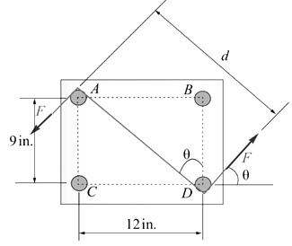
Four
-diameter pegs are attached to a board as shown. Two strings are passed around the pegs and pulled with the forces indicated. (a) Determine the resultant couple acting on the board. (b) If only one string is used, around which pegs should it pass and in what directions should it be pulled to create the same couple with the minimum tension in the string? (c) What is the value of that minimum tension?
Want to see the full answer?
Check out a sample textbook solution
Chapter 3 Solutions
Statics and Mechanics of Materials
Additional Engineering Textbook Solutions
Vector Mechanics for Engineers: Statics and Dynamics
Manufacturing Engineering & Technology
Fluid Mechanics Fundamentals And Applications
Automotive Technology: Principles, Diagnosis, and Service (5th Edition)
Vector Mechanics for Engineers: Dynamics
Machine Elements in Mechanical Design (6th Edition) (What's New in Trades & Technology)


- Two strings are passed around the four 1-in.-diameter pegs that are attached to a board and pulled with the forces shown. (a) find the magnitude and direction of the resultant couple acting on the board. (b) If only the string that passed around pigs B and C is used, what is the minimum value of the tension required to create the same couple as in (a).arrow_forward.******** -5 in. A 30-Ib vertical force P is applied at A to the bracket shown., which is held by screws B and C. (a) Replace 2 in. P with an equivalent force-couple system at B. (b) B Find the two horizontal forces at B and C that are 3 in equivalent to the couple obtained in part a. ********* ******** *arrow_forward1. A machine component is subjected to the forces and couples shown. a- Determine the equivalent force-couple system for the given loading condition. b- If the component is to be held in place by a single rivet that can resist a force but not a couple. Determine the location of the rivet hole if it is to be located (i) on line FG, (ii) on line GH. 120 N 240 mm 200 N 70° 15 D Fi 50 mm 42 N-m 80 N 520 mm C 60 N 180 mm Hi 40 N-m G В 50 mm 50 mm 640 mmarrow_forward
- The forces shown form a couple. Which ONE of the following equations can be used to replace the shown couple with an equivalent couple acting at points A and B. HINT: Choose clockwise as negative and counterclockwise as positive. 50 mm AB 40 N 200 mm 40 N Ⓒa. 40 N(200 mm) - F(50 mm) = 0 b. -40 N(200 mm) + F(50 mm) = c. +40 N(200 mm) + F(50 mm) = 0 d. 50 N(200 mm) - F(40 mm) = 0 e. 40 N(50 mm) - F(200 mm) = 0 Clear my choicearrow_forwardForce P and couple M are applied at A as shown. 1. Suppose an equivalent system was made such that only force at B and a couple are present. What gives the magnitude of force at B and the couple in the equivalent system? 2. If the force P and couple M is to be replaced with a single force, where is the point of application of this single force along bar ABCD in order to have the same external effect as the original set of force P and couple M? (How many m to the left or right of B)arrow_forwardThe shearing forces exerted on the cross section of a steel channel can be represented by a 900-N vertical force and two 250-N horizontal forces as shown. Replace this force and couple with a single force F applied at point C , and determine the distance x from C to line BD . (Point Cis defined as the shear center of the section.)arrow_forward
- 120 Rigid Bodies: Equivalent Systems of Forces 3.74 Two parallel 40-N forces are applied to a lever as shown. Deter- mine the moment of the couple formed by the two forces (a) by resolving each force into horizontal and vertical components and adding the moments of the two resulting couples, (b) by using the perpendicular distance between the two forces, (e) by summing the moments of the two forces about point A. 20° 40 N The tw hafts of a sneed-reducer unit are subiected to couples mag d = 1 Ib I ad M "couples with a gle quivalent couple, specifts mag- .ade and the dire 40 N 270 mm w It, respectiv y. Pplace its axis. 55° 390 mm A O Fig. P3.74arrow_forwardCurrent Attempt in Progress Your answer is partially correct. The flanged steel cantilever beam with riveted bracket is subjected to the couple and two forces shown, and their effect on the design of the attachment at A must be determined. Replace the two forces and couple by an equivalent couple M and resultant R at A. The couple is positive if counterclockwise, negative if clockwise. 1.98 kN 0.48 m 1.60 m 71° 0.18 m 0.18 m 610 N.m L--x 6. 1.40 kN Answers: M= i 2.133 kN-m R = ( 1.9 i+ 1. 25 j) kN eTextbook and Media Save for Laterarrow_forward2. A person's arm is used for ergonomic studies. If the distance of the AB, BC, and CD segments are 35.0 mm, 28.0 mm, and 19.0 mm, respectively, and the model is holding a small 1.5-lb load on the distal metacarpals of her hand . Determine the magnitude and direction of the moment of force with respect to a) to the shoulder joint, b) to the olecranon joint, c) to the carpal joint.arrow_forward
- A machine component is subjected to the forces and couples shown. The component is to be held in place by a single rivet that can resist a force but not a couple. For P = 0, determine the location of the rivet hole if it is to be located (a) on line FG , (b) on line GH.arrow_forwardIn a manufacturing operation, three holes are drilled simultaneously in a workpiece. If the holes are perpendicular to the surfaces of the workpiece, replace the couples applied to the drills with a single equivalent couple, specifying its magnitude and the direction of its axis.arrow_forwardThe manufacturer of an automobile is considering the two designs shown for the vehicle's lug nut wrench. Forcés F4, Fc, Qu, and Qc are applied by the user to the wrench; these forces are perpendicular to plane ABCD and are to be couples., (a) If FA= QA = 150 N, determine Fc and Qc, and for each wrench, determine the moment of the couple. (b) If a moment about the x axis at point D of 12000N-mm is required to loosen the lug nut, determine the values of F4, Fc. Qu, and Qc. 40 mm 40 25 mm 25 mm Tec 25 mm (a)arrow_forward
 Elements Of ElectromagneticsMechanical EngineeringISBN:9780190698614Author:Sadiku, Matthew N. O.Publisher:Oxford University Press
 Mechanics of Materials (10th Edition)Mechanical EngineeringISBN:9780134319650Author:Russell C. HibbelerPublisher:PEARSON
 Thermodynamics: An Engineering ApproachMechanical EngineeringISBN:9781259822674Author:Yunus A. Cengel Dr., Michael A. BolesPublisher:McGraw-Hill Education
 Control Systems EngineeringMechanical EngineeringISBN:9781118170519Author:Norman S. NisePublisher:WILEY
 Mechanics of Materials (MindTap Course List)Mechanical EngineeringISBN:9781337093347Author:Barry J. Goodno, James M. GerePublisher:Cengage Learning
 Engineering Mechanics: StaticsMechanical EngineeringISBN:9781118807330Author:James L. Meriam, L. G. Kraige, J. N. BoltonPublisher:WILEY