
Vector Mechanics for Engineers: Statics and Dynamics
12th Edition
ISBN: 9781259638091
Author: Ferdinand P. Beer, E. Russell Johnston Jr., David Mazurek, Phillip J. Cornwell, Brian Self
Publisher: McGraw-Hill Education
expand_more
expand_more
format_list_bulleted
Concept explainers
Videos
Textbook Question
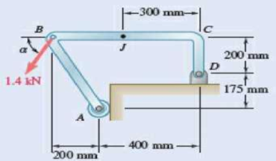
Chapter 7.1, Problem 7.3P
Determine the internal forces at point J when α = 90°.
Expert Solution & Answer
Want to see the full answer?
Check out a sample textbook solution
Students have asked these similar questions
Determine the internal forces at point J, with alpha = 0°
Determine the internal forces at point J when a= = 90°.
with the following modifications:
Replace the vertical 6kN at point B with a horizontal force 6kN acting to the right at the same point.
Chapter 7 Solutions
Vector Mechanics for Engineers: Statics and Dynamics
Ch. 7.1 - 7.1 and 7.2 Determine the internal forces (axial...Ch. 7.1 - 7.1 and 7.2 Determine the internal forces (axial...Ch. 7.1 - Determine the internal forces at point J when =...Ch. 7.1 - Fig. P7.3 and P7.4 7.4 Determine the internal...Ch. 7.1 - Determine the internal forces at point J when =...Ch. 7.1 - Fig. P7.5 and P7.6 7.6 Determine the internal...Ch. 7.1 - An archer aiming at a target is pulling with a...Ch. 7.1 - For the bow of Prob. 7.7, determine the magnitude...Ch. 7.1 - A semicircular rod is loaded as shown. Determine...Ch. 7.1 - A semicircular rod is loaded as shown. Determine...
Ch. 7.1 - A semicircular rod is loaded as shown. Determine...Ch. 7.1 - Fig. P7.11 and P7.12 7.12 A semicircular rod is...Ch. 7.1 - The axis of the curved member AB is a parabola...Ch. 7.1 - Knowing that the axis of the curved member AB is a...Ch. 7.1 - Prob. 7.15PCh. 7.1 - Fig. P7.15 and P7.16 7.16 Knowing that the radius...Ch. 7.1 - Prob. 7.17PCh. 7.1 - For the frame of Prob. 7.17, determine the...Ch. 7.1 - Knowing that the radius of each pulley is 200 mm...Ch. 7.1 - Fig. P7.19 and P7.20 7.20 Knowing that the radius...Ch. 7.1 - and 7.22 A force P is applied to a bent rod that...Ch. 7.1 - and 7.22 A force P is applied to a bent rod that...Ch. 7.1 - Prob. 7.23PCh. 7.1 - For the rod of Prob. 7.23, determine the magnitude...Ch. 7.1 - A semicircular rod of weight W and uniform cross...Ch. 7.1 - Prob. 7.26PCh. 7.1 - Prob. 7.27PCh. 7.1 - 7.27 and 7.28 A half section of pipe rests on a...Ch. 7.2 - 7.29 through 7.32 For the beam and loading shown,...Ch. 7.2 - 7.29 through 7.32 For the beam and loading shown,...Ch. 7.2 - Prob. 7.31PCh. 7.2 - 7.29 through 7.32 For the beam and loading shown,...Ch. 7.2 - 7.33 and 7.34 For the beam and loading shown, (a)...Ch. 7.2 - 7.33 and 7.34 For the beam and loading shown, (a)...Ch. 7.2 - 7.35 and 7.36 For the beam and loading shown, (a)...Ch. 7.2 - Prob. 7.36PCh. 7.2 - 7.37 and 7.38 For the beam and loading shown, (a)...Ch. 7.2 - 7.37 and 7.38 For the beam and loading shown, (a)...Ch. 7.2 - For the beam and loading shown, (a) draw the shear...Ch. 7.2 - For the beam and loading shown, (a) draw the shear...Ch. 7.2 - Prob. 7.41PCh. 7.2 - For the beam and loading shown, (a) draw the shear...Ch. 7.2 - Assuming the upward reaction of the ground on beam...Ch. 7.2 - Solve Problem 7.43 knowing that P = 3wa. PROBLEM...Ch. 7.2 - Assuming the upward reaction of the ground on beam...Ch. 7.2 - Prob. 7.46PCh. 7.2 - Assuming the upward reaction of the ground on beam...Ch. 7.2 - Assuming the upward reaction of the ground on beam...Ch. 7.2 - Draw the shear and bending-moment diagrams for the...Ch. 7.2 - Draw the shear and bending-moment diagrams for the...Ch. 7.2 - Draw the shear and bending-moment diagrams for the...Ch. 7.2 - Draw the shear and bending-moment diagrams for the...Ch. 7.2 - Two small channel sections DF and EH have been...Ch. 7.2 - Solve Prob. 7.53 when = 60. PROBLEM 7.53 Two...Ch. 7.2 - For the structural member of Prob. 7.53, determine...Ch. 7.2 - For the beam of Prob. 7.43, determine (a) the...Ch. 7.2 - Determine (a) the distance a for which the maximum...Ch. 7.2 - For the beam and loading shown, determine (a) the...Ch. 7.2 - A uniform beam is to be picked up by crane cables...Ch. 7.2 - Knowing that P = Q = 150 lb, determine (a) the...Ch. 7.2 - Prob. 7.61PCh. 7.2 - Prob. 7.62PCh. 7.3 - Using the method of Sec. 7.3, solve Prob. 7.29....Ch. 7.3 - Prob. 7.64PCh. 7.3 - Prob. 7.65PCh. 7.3 - Using the method of Sec. 7.3, solve Prob. 7.32....Ch. 7.3 - Using the method of Sec. 7.3, solve Prob. 7.33....Ch. 7.3 - Using the method of Sec. 7.3, solve Prob. 7.34....Ch. 7.3 - 7.69 and 7.70 For the beam and loading shown, (a)...Ch. 7.3 - 7.69 and 7.70 For the beam and loading shown, (a)...Ch. 7.3 - Using the method of Sec. 7.3, solve Prob. 7.39....Ch. 7.3 - Using the method of Sec. 7.3, solve Prob. 7.40....Ch. 7.3 - Using the method of Sec. 7.3, solve Prob. 7.41....Ch. 7.3 - Using the method of Sec. 7.3, solve Prob. 7.42....Ch. 7.3 - 7.75 and 7.76 For the beam and loading shown, (a)...Ch. 7.3 - Prob. 7.76PCh. 7.3 - For the beam and loading shown, (a) draw the shear...Ch. 7.3 - For the beam and loading shown, (a) draw the shear...Ch. 7.3 - For the beam and loading shown, (a) draw the shear...Ch. 7.3 - For the beam and loading shown, (a) draw the shear...Ch. 7.3 - For the beam and loading shown, (a) draw the shear...Ch. 7.3 - For the beam and loading shown, (a) draw the shear...Ch. 7.3 - (a) Draw the shear and bending-moment diagrams for...Ch. 7.3 - Solve Prob. 7.83 assuming that the 300-lb force...Ch. 7.3 - For the beam and loading shown, (a) write the...Ch. 7.3 - For the beam and loading shown, (a) write the...Ch. 7.3 - For the beam and loading shown, (a) write the...Ch. 7.3 - Prob. 7.88PCh. 7.3 - The beam AB supports the uniformly distributed...Ch. 7.3 - Solve Prob. 7.89 assuming that the uniformly...Ch. 7.3 - The beam AB is subjected to the uniformly...Ch. 7.3 - Solve Prob. 7.91 assuming that the uniformly...Ch. 7.4 - Three loads are suspended as shown from the cable...Ch. 7.4 - Knowing that the maximum tension in cable ABCDE is...Ch. 7.4 - Prob. 7.95PCh. 7.4 - Fig. P7.95 and P7.96 7.96 If dA = dc = 6 ft,...Ch. 7.4 - Knowing that dc = 5 m, determine (a) the distances...Ch. 7.4 - Fig. P7.97 and P7.98 7.98 Determine (a) distance...Ch. 7.4 - Knowing that dc = 9 ft, determine (a) the...Ch. 7.4 - Fig. P7.99 and P7.100 7.100 Determine (a) the...Ch. 7.4 - Knowing that mB = 70 kg and mC = 25 kg, determine...Ch. 7.4 - Prob. 7.102PCh. 7.4 - Prob. 7.103PCh. 7.4 - Prob. 7.104PCh. 7.4 - Prob. 7.105PCh. 7.4 - If a = 4 m, determine the magnitudes of P and Q...Ch. 7.4 - An electric wire having a mass per unit length of...Ch. 7.4 - Prob. 7.108PCh. 7.4 - Prob. 7.109PCh. 7.4 - Prob. 7.110PCh. 7.4 - Prob. 7.111PCh. 7.4 - Two cables of the same gauge are attached to a...Ch. 7.4 - Prob. 7.113PCh. 7.4 - Prob. 7.114PCh. 7.4 - Prob. 7.115PCh. 7.4 - Prob. 7.116PCh. 7.4 - Prob. 7.117PCh. 7.4 - Prob. 7.118PCh. 7.4 - Prob. 7.119PCh. 7.4 - Prob. 7.120PCh. 7.4 - Prob. 7.121PCh. 7.4 - Prob. 7.122PCh. 7.4 - Prob. 7.123PCh. 7.4 - Prob. 7.124PCh. 7.4 - Prob. 7.125PCh. 7.4 - Prob. 7.126PCh. 7.5 - A 25-ft chain with a weight of 30 lb is suspended...Ch. 7.5 - A 500-ft-long aerial tramway cable having a weight...Ch. 7.5 - Prob. 7.129PCh. 7.5 - Prob. 7.130PCh. 7.5 - Prob. 7.131PCh. 7.5 - Prob. 7.132PCh. 7.5 - Prob. 7.133PCh. 7.5 - Prob. 7.134PCh. 7.5 - Prob. 7.135PCh. 7.5 - Prob. 7.136PCh. 7.5 - Prob. 7.137PCh. 7.5 - Prob. 7.138PCh. 7.5 - Prob. 7.139PCh. 7.5 - Prob. 7.140PCh. 7.5 - Prob. 7.141PCh. 7.5 - Prob. 7.142PCh. 7.5 - Prob. 7.143PCh. 7.5 - Prob. 7.144PCh. 7.5 - Prob. 7.145PCh. 7.5 - Prob. 7.146PCh. 7.5 - Prob. 7.147PCh. 7.5 - Prob. 7.148PCh. 7.5 - Prob. 7.149PCh. 7.5 - Prob. 7.150PCh. 7.5 - A cable has a mass per unit length of 3 kg/m and...Ch. 7.5 - Prob. 7.152PCh. 7.5 - Prob. 7.153PCh. 7 - Knowing that the turnbuckle has been tightened...Ch. 7 - Knowing that the turnbuckle has been tightened...Ch. 7 - Two members, each consisting of a straight and a...Ch. 7 - Knowing that the radius of each pulley is 150 mm,...Ch. 7 - Prob. 7.158RPCh. 7 - For the beam and loading shown, (a) draw the shear...Ch. 7 - For the beam and loading shown, (a) draw the shear...Ch. 7 - Prob. 7.161RPCh. 7 - Prob. 7.162RPCh. 7 - Prob. 7.163RPCh. 7 - Prob. 7.164RPCh. 7 - A 10-ft rope is attached to two supports A and B...
Knowledge Booster


Learn more about
Need a deep-dive on the concept behind this application? Look no further. Learn more about this topic, mechanical-engineering and related others by exploring similar questions and additional content below.Similar questions
- Determine the internal forces at point J of the structurearrow_forwardThe device shown is a part of an automobile seat-back-release mechanism. The part is subjected to the 4.0-N force exerted at A and a 380-N·mm restoring moment exerted by a hidden torsional spring. Determine the y-intercept of the line of action of the single equivalent force. Your answer will be positive if the intercept is above O and negative if below O.arrow_forwardThe line of action of the 3110-lb force runs through the points A and B as shown in the figure. Determine the x and y scalar components of F. A (-7, -2) Answers: Fx- Fy- y, m B (8,4) F = 3110 lb -x, m lb lbarrow_forward
- For the same problem given in Part A, if the support at B creates a reaction force Bx and By as shown, determine these reaction forces. Assume B is located at 3 m from the origin O along the z-axis Z X By 3 m O 6 m 3.5 m Bx G 3.5 m A 2 m Yarrow_forwardResolve the 360-N force into components along the cables AB and AC. Use α = 55° and β= 30°.arrow_forwardThe convergent system of 4 forces acting on an absolutely rigid body is balanced (ΣFKY = 0). Determine the projection of the fourth force on the Oy axis if F1y = 160.0 kN; F2y = -46.0 kN; F3y = 36.0 kN;.arrow_forward
- The line of action of the 4360-lb force runs through the points A and B as shown in the figure. Determine the x and y scalar components of F. y, m B (11, 8) F = 4360 lb -x, m lb lb Answers: Fx= i i LL A (-10,-4) ||arrow_forward4. A machine component is subjected to the forces and couples as shown. If P = 60 N, determine the magnitude and direction of the resultant force as well as the location where the resultant force passes through vertical line GF and horizontal line GH. 15 200 N 50 mm 520 mm E 50 mm 240 mm 42 N-m D 120 N 70⁰ 40 N-m 640 mm H 80 N 180 mm B +50mm Ans: (a) 0.365 m above G (b) 0.227 m to the right of Garrow_forwardResolve the forces F1=6 kN and F2=6 kN into components acting along the u and v axes and determine the magnitudes of the components. The angles are given as 01=26, 02=89 and 03=52. F1 F2 |(F)ul= kN (F)y = kN (F2)u = kN (F2)y = kNarrow_forward
- Determine the moment of the three forces about the point A. F = 30 lb F = 20 lb/ 30% 70° 50 lb < 60° 4 in. 1 in. -3.5 in:-arrow_forwardCombine the two forces P and T, which act on the fixed structure at B, into a single equivalent force R P = 800 lb В y T = 600 lb 6 --x A a C/60° DI 3'-arrow_forwardDetermine the internal forces (axial force, shear force, and bending moment) at point j of the indicated structure, teta = 90 º,arrow_forward
arrow_back_ios
SEE MORE QUESTIONS
arrow_forward_ios
Recommended textbooks for you
 Elements Of ElectromagneticsMechanical EngineeringISBN:9780190698614Author:Sadiku, Matthew N. O.Publisher:Oxford University Press
 Mechanics of Materials (10th Edition)Mechanical EngineeringISBN:9780134319650Author:Russell C. HibbelerPublisher:PEARSON
 Thermodynamics: An Engineering ApproachMechanical EngineeringISBN:9781259822674Author:Yunus A. Cengel Dr., Michael A. BolesPublisher:McGraw-Hill Education
 Control Systems EngineeringMechanical EngineeringISBN:9781118170519Author:Norman S. NisePublisher:WILEY
 Mechanics of Materials (MindTap Course List)Mechanical EngineeringISBN:9781337093347Author:Barry J. Goodno, James M. GerePublisher:Cengage Learning
 Engineering Mechanics: StaticsMechanical EngineeringISBN:9781118807330Author:James L. Meriam, L. G. Kraige, J. N. BoltonPublisher:WILEY
Elements Of Electromagnetics
Mechanical Engineering
ISBN:9780190698614
Author:Sadiku, Matthew N. O.
Publisher:Oxford University Press
Mechanics of Materials (10th Edition)
Mechanical Engineering
ISBN:9780134319650
Author:Russell C. Hibbeler
Publisher:PEARSON
Thermodynamics: An Engineering Approach
Mechanical Engineering
ISBN:9781259822674
Author:Yunus A. Cengel Dr., Michael A. Boles
Publisher:McGraw-Hill Education
Control Systems Engineering
Mechanical Engineering
ISBN:9781118170519
Author:Norman S. Nise
Publisher:WILEY
Mechanics of Materials (MindTap Course List)
Mechanical Engineering
ISBN:9781337093347
Author:Barry J. Goodno, James M. Gere
Publisher:Cengage Learning
Engineering Mechanics: Statics
Mechanical Engineering
ISBN:9781118807330
Author:James L. Meriam, L. G. Kraige, J. N. Bolton
Publisher:WILEY
EVERYTHING on Axial Loading Normal Stress in 10 MINUTES - Mechanics of Materials; Author: Less Boring Lectures;https://www.youtube.com/watch?v=jQ-fNqZWrNg;License: Standard YouTube License, CC-BY