
Vector Mechanics for Engineers: Statics
12th Edition
ISBN: 9781259977268
Author: Ferdinand P. Beer, E. Russell Johnston Jr., David Mazurek
Publisher: McGraw-Hill Education
expand_more
expand_more
format_list_bulleted
Concept explainers
Videos
Textbook Question
Chapter 7.5, Problem 7.133P
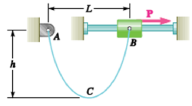
A 20-m length of wire having a mass per unit length of 0.2 kg/m is attached to a fixed support at A and to a collar at B. Neglecting the effect of friction, determine (a) the sag h for which L = 15 m, (b) the corresponding force P.
Expert Solution & Answer
Want to see the full answer?
Check out a sample textbook solution
Students have asked these similar questions
frictionless cylinders A = 2.0 kg and B= 1.0kg. Force P is the smallest force that will lift cylinder A off the horizontal surface.
radius of b = 9.95 m
1. Determine the value of P.
2. What is the angle of the tangent line at the point of tangency of the two cylinders.
A 20-m length of wire having a mass per unit length of 0.2 kg/m is attached to a fixed support at A and to a collar at B . Neglecting the effect of friction, determine (a) the sag h for which L = 15m, (b) the corresponding force P.
A spring of constant 15 kN/m connects points C and F of the linkage shown. Neglecting the weight of the spring and linkage, determine the force in the spring and the vertical motion of point G when a vertical downward 120-N force is applied (a) at point C ,( b) at points C and H.
Chapter 7 Solutions
Vector Mechanics for Engineers: Statics
Ch. 7.1 - 7.1 and 7.2 Determine the internal forces (axial...Ch. 7.1 - Prob. 7.2PCh. 7.1 - Determine the internal forces at point J when =...Ch. 7.1 - Fig. P7.3 and P7.4 7.4 Determine the internal...Ch. 7.1 - Determine the internal forces at point J when =...Ch. 7.1 - Fig. P7.5 and P7.6 7.6 Determine the internal...Ch. 7.1 - An archer aiming at a target is pulling with a...Ch. 7.1 - For the bow of Prob. 7.7, determine the magnitude...Ch. 7.1 - A semicircular rod is loaded as shown. Determine...Ch. 7.1 - A semicircular rod is loaded as shown. Determine...
Ch. 7.1 - A semicircular rod is loaded as shown. Determine...Ch. 7.1 - Fig. P7.11 and P7.12 7.12 A semicircular rod is...Ch. 7.1 - The axis of the curved member AB is a parabola...Ch. 7.1 - Knowing that the axis of the curved member AB is a...Ch. 7.1 - Knowing that the radius of each pulley is 120 mm...Ch. 7.1 - Fig. P7.15 and P7.16 7.16 Knowing that the radius...Ch. 7.1 - A 5-in.-diameter pipe is supported every 9 ft by a...Ch. 7.1 - For the frame of Prob. 7.17, determine the...Ch. 7.1 - Knowing that the radius of each pulley is 200 mm...Ch. 7.1 - Fig. P7.19 and P7.20 7.20 Knowing that the radius...Ch. 7.1 - and 7.22 A force P is applied to a bent rod that...Ch. 7.1 - and 7.22 A force P is applied to a bent rod that...Ch. 7.1 - A quarter-circular rod of weight W and uniform...Ch. 7.1 - For the rod of Prob. 7.23, determine the magnitude...Ch. 7.1 - A semicircular rod of weight W and uniform cross...Ch. 7.1 - A semicircular rod of weight W and uniform cross...Ch. 7.1 - 7.27 and 7.28 A half section of pipe rests on a...Ch. 7.1 - 7.27 and 7.28 A half section of pipe rests on a...Ch. 7.2 - 7.29 through 7.32 For the beam and loading shown,...Ch. 7.2 - 7.29 through 7.32 For the beam and loading shown,...Ch. 7.2 - 7.29 through 7.32 For the beam and loading shown,...Ch. 7.2 - 7.29 through 7.32 For the beam and loading shown,...Ch. 7.2 - 7.33 and 7.34 For the beam and loading shown, (a)...Ch. 7.2 - 7.33 and 7.34 For the beam and loading shown, (a)...Ch. 7.2 - 7.35 and 7.36 For the beam and loading shown, (a)...Ch. 7.2 - 7.35 and 7.36 For the beam and loading shown, (a)...Ch. 7.2 - 7.37 and 7.38 For the beam and loading shown, (a)...Ch. 7.2 - 7.37 and 7.38 For the beam and loading shown, (a)...Ch. 7.2 - For the beam and loading shown, (a) draw the shear...Ch. 7.2 - For the beam and loading shown, (a) draw the shear...Ch. 7.2 - For the beam and loading shown, (a) draw the shear...Ch. 7.2 - For the beam and loading shown, (a) draw the shear...Ch. 7.2 - Assuming the upward reaction of the ground on beam...Ch. 7.2 - Solve Problem 7.43 knowing that P = 3wa. PROBLEM...Ch. 7.2 - Assuming the upward reaction of the ground on beam...Ch. 7.2 - Solve Prob. 7.45 assuming that the 12-kip load has...Ch. 7.2 - Assuming the upward reaction of the ground on beam...Ch. 7.2 - Prob. 7.48PCh. 7.2 - Draw the shear and bending-moment diagrams for the...Ch. 7.2 - Draw the shear and bending-moment diagrams for the...Ch. 7.2 - Draw the shear and bending-moment diagrams for the...Ch. 7.2 - Draw the shear and bending-moment diagrams for the...Ch. 7.2 - Two small channel sections DF and EH have been...Ch. 7.2 - Solve Prob. 7.53 when = 60. PROBLEM 7.53 Two...Ch. 7.2 - For the structural member of Prob. 7.53, determine...Ch. 7.2 - For the beam of Prob. 7.43, determine (a) the...Ch. 7.2 - Determine (a) the distance a for which the maximum...Ch. 7.2 - For the beam and loading shown, determine (a) the...Ch. 7.2 - A uniform beam is to be picked up by crane cables...Ch. 7.2 - Knowing that P = Q = 150 lb, determine (a) the...Ch. 7.2 - Knowing that P = Q = 150 lb, determine (a) the...Ch. 7.2 - In order to reduce the bending moment in the...Ch. 7.3 - Using the method of Sec. 7.3, solve Prob. 7.29....Ch. 7.3 - Prob. 7.64PCh. 7.3 - Using the method of Sec. 7.3, solve Prob. 7.31....Ch. 7.3 - Prob. 7.66PCh. 7.3 - Using the method of Sec. 7.3, solve Prob. 7.33....Ch. 7.3 - Using the method of Sec. 7.3, solve Prob. 7.34....Ch. 7.3 - 7.69 and 7.70 For the beam and loading shown, (a)...Ch. 7.3 - 7.69 and 7.70 For the beam and loading shown, (a)...Ch. 7.3 - Using the method of Sec. 7.3, solve Prob. 7.39....Ch. 7.3 - Using the method of Sec. 7.3, solve Prob. 7.40....Ch. 7.3 - Using the method of Sec. 7.3, solve Prob. 7.41....Ch. 7.3 - Using the method of Sec. 7.3, solve Prob. 7.42....Ch. 7.3 - 7.75 and 7.76 For the beam and loading shown, (a)...Ch. 7.3 - Prob. 7.76PCh. 7.3 - For the beam and loading shown, (a) draw the shear...Ch. 7.3 - For the beam and loading shown, (a) draw the shear...Ch. 7.3 - For the beam and loading shown, (a) draw the shear...Ch. 7.3 - For the beam and loading shown, (a) draw the shear...Ch. 7.3 - For the beam and loading shown, (a) draw the shear...Ch. 7.3 - For the beam and loading shown, (a) draw the shear...Ch. 7.3 - (a) Draw the shear and bending-moment diagrams for...Ch. 7.3 - Solve Prob. 7.83 assuming that the 300-lb force...Ch. 7.3 - For the beam and loading shown, (a) write the...Ch. 7.3 - For the beam and loading shown, (a) write the...Ch. 7.3 - For the beam and loading shown, (a) write the...Ch. 7.3 - For the beam and loading shown, (a) write the...Ch. 7.3 - The beam AB supports the uniformly distributed...Ch. 7.3 - Solve Prob. 7.89 assuming that the uniformly...Ch. 7.3 - The beam AB is subjected to the uniformly...Ch. 7.3 - Prob. 7.92PCh. 7.4 - Three loads are suspended as shown from the cable...Ch. 7.4 - Knowing that the maximum tension in cable ABCDE is...Ch. 7.4 - If dA = 8 ft and dc = 10 ft, determine the...Ch. 7.4 - Prob. 7.96PCh. 7.4 - Knowing that dc = 5 m, determine (a) the distances...Ch. 7.4 - Prob. 7.98PCh. 7.4 - Knowing that dc = 9 ft, determine (a) the...Ch. 7.4 - Prob. 7.100PCh. 7.4 - Knowing that mB = 70 kg and mC = 25 kg, determine...Ch. 7.4 - Fig. P7.101 and P7.102 7.102 Knowing that mB = 18...Ch. 7.4 - Cable ABC supports two loads as shown. Knowing...Ch. 7.4 - Prob. 7.104PCh. 7.4 - If a = 3 m, determine the magnitudes of P and Q...Ch. 7.4 - If a = 4 m, determine the magnitudes of P and Q...Ch. 7.4 - An electric wire having a mass per unit length of...Ch. 7.4 - The total mass of cable ACB is 20 kg. Assuming...Ch. 7.4 - The center span of the George Washington Bridge,...Ch. 7.4 - The center span of the Verrazano-Narrows Bridge...Ch. 7.4 - Each cable of the Golden Gate Bridge supports a...Ch. 7.4 - Two cables of the same gauge are attached to a...Ch. 7.4 - A 76-m length of wire having a mass per unit...Ch. 7.4 - A cable of length L + is suspended between two...Ch. 7.4 - The total mass of cable AC is 25 kg. Assuming that...Ch. 7.4 - Cable ACB supports a load uniformly distributed...Ch. 7.4 - Each cable of the side spans of the Golden Gate...Ch. 7.4 - A steam pipe weighing 45 lb/ft that passes between...Ch. 7.4 - A cable AB of span L and a simple beam AB of the...Ch. 7.4 - Making use of the property established in Prob....Ch. 7.4 - 7.120 through 7.123 Making use of the property...Ch. 7.4 - 7.120 through 7.123 Making use of the property...Ch. 7.4 - Prob. 7.123PCh. 7.4 - Prob. 7.124PCh. 7.4 - Using the property indicated in Prob. 7.124,...Ch. 7.4 - If the weight per unit length of the cable AB is...Ch. 7.5 - A 25-ft chain with a weight of 30 lb is suspended...Ch. 7.5 - A 500-ft-long aerial tramway cable having a weight...Ch. 7.5 - A 40-m cable is strung as shown between two...Ch. 7.5 - A 50-m steel surveying tape has a mass of 1.6 kg....Ch. 7.5 - Prob. 7.131PCh. 7.5 - Prob. 7.132PCh. 7.5 - A 20-m length of wire having a mass per unit...Ch. 7.5 - Determine the sag of a 30-ft chain that is...Ch. 7.5 - Prob. 7.135PCh. 7.5 - Prob. 7.136PCh. 7.5 - A cable weighing 2 lb/ft is suspended between two...Ch. 7.5 - Prob. 7.138PCh. 7.5 - Prob. 7.139PCh. 7.5 - Fig. P7.139 and P7.140 7.140 A motor M is used to...Ch. 7.5 - Prob. 7.141PCh. 7.5 - Prob. 7.142PCh. 7.5 - Prob. 7.143PCh. 7.5 - Prob. 7.144PCh. 7.5 - To the left of point B, the long cable ABDE rests...Ch. 7.5 - Fig. P7.145 and P7.146 7.146 To the left of point...Ch. 7.5 - The 10-ft cable AB is attached to two collars as...Ch. 7.5 - Prob. 7.148PCh. 7.5 - Prob. 7.149PCh. 7.5 - (a) Determine the maximum allowable horizontal...Ch. 7.5 - A cable has a mass per unit length of 3 kg/m and...Ch. 7.5 - Determine the sag-to-span ratio for which the...Ch. 7.5 - Prob. 7.153PCh. 7 - Knowing that the turnbuckle has been tightened...Ch. 7 - Knowing that the turnbuckle has been tightened...Ch. 7 - Two members, each consisting of a straight and a...Ch. 7 - Knowing that the radius of each pulley is 150 mm,...Ch. 7 - For the beam shown, determine (a) the magnitude P...Ch. 7 - For the beam and loading shown, (a) draw the shear...Ch. 7 - For the beam and loading shown, (a) draw the shear...Ch. 7 - For the beam shown, draw the shear and...Ch. 7 - The beam AB, which lies on the ground, supports...Ch. 7 - Two loads are suspended as shown from the cable...Ch. 7 - A wire having a mass per unit length of 0.65 kg/m...Ch. 7 - A 10-ft rope is attached to two supports A and B...
Knowledge Booster


Learn more about
Need a deep-dive on the concept behind this application? Look no further. Learn more about this topic, mechanical-engineering and related others by exploring similar questions and additional content below.Similar questions
- The L-shaped member ACB is supported by a pin and bracket at C and by an inextensible cord attached at A and B and passing over a frictionless pulley at D. The tension may be assumed to be the same in portions AD and BD of the cord. If the magnitudes of the forces applied at A and B are, respectively, P = 25 lb and Q = 0, determine (a) the tension in the cord, (b) the reaction at Carrow_forward3 1 kN 4 esc 2 kN Во C 2 kN Do 1 E 180 mm 1 kN F G 2m 2m 2m 2m 2m 2m 160 mm B H C K A 90 mm 0 m 1 m 1m 1m L 1m 240 N 31 PROBLEM 6.131 Arm ABC is connected by pins to a collar at B and to crank CD at C. Neglecting the effect of friction, determine the couple M required to hold the system in equilibrium when 0=0. ▸ % PROBLEM 6.21 L Determine the force in each of the members located to the left of FG for the scissors roof truss shown. State whether each member is in tension or compression. A 6 & 7 * 8 of J O Jul 17 8:13 xarrow_forward4. A cylinder weighing 400lb is held against a smooth incline by means of of a weightless rod AB. Determine the forces P and N exerted on the cylinder by the rod and the incdine. W=400b.arrow_forward
- An athlete of 60 kg and 1.70 m tall performs the ring exercise called "the Christ", in which he keeps his body immobile with his arms extended horizontally as shown in Fig.-Prob.17(a). The angle with the vertical of the cords from which the rings hang is theta = 10. (a) Determine the tension T in the cords holding the rings. (b) Considering each arm of the athlete as a rigid horizontal bar subjected to the forces indicated in Fig.-Prob.17(b), calculate the value of the components RX and RY, the value of the reaction “R” and of the beta angle.- W is the weight of the arm, applied in the middle of its length.- R is the reaction at the shoulder joint O.- RX and RY are the horizontal and vertical components respectively of the reactionapplied at the shoulder joint O.- Note: Consider that the mass of each arm of the athlete is 3% of the total mass, and thatthe length of the arm is equal to 35% of its height. Fig.-Prob.17(a): Man performing the position of "The Christ"Fig.-Prob.17(b):…arrow_forwardThe uniform 10 kg rod AB is supported by a ball and socket joint at A and by the cord CG that is attached to the midpoint G of the rod. Knowing that the rod leans against a frictionless vertical wall at B and that the tension in the cord CG, TCG=52.1 N, determine the following a.) Which of the following best shows the equivalent force-couple set at point A of the tension at cord CG, TCG? Choices: a F= -36.8 N i + 24.5 N j - 27.6 N k M = -7.36 Nm i - 11.03 Nm j b F= -36.8 N i + 24.5 N j - 27.6 N k M = -7.36 Nm i - 29.4 Nm k c F= 36.8 N i - 24.5 N j + 27.6 N k M = 7.36 Nm i + 11.03 Nm j d F= 36.8 N i - 24.5 N j + 27.6 N k M = 7.36 Nm i + 29.4 Nm k b.) Which of the following moments is equal to zero? Choices: The moment of the tension in cord CG, TCG about point OThe moment of the tension in cord CG, TCG about point AThe moment of the tension in cord CG, TCG about point BThe moment of the tension in cord CG, TCG about axis ABarrow_forwardA freight wagon is at rest on a track at an angle of 25o to the vertical. The gross weight of the wagon and its load is 36kN and acts at a point 750 mm from the track, in the middle between the two axles. The wagon is held by a cable 600 mm from the track. Determine the traction on the cable and the reaction on each pair of wheels.arrow_forward
- A 81-lb sheet of plywood rests on two small wooden blocks as shown. It is allowed to lean 20° from the vertical under the action of a force P which is perpendicular to the sheet. Friction at all surfaces of blocks A and B is sufficient to prevent slipping. Determine the magnitude P and the vertical reaction forces at A and B. D 4.0' 1.0' E A 5.2' DE = 3.3 ft 1.8' B 1 -20⁰arrow_forwardA 550 N cylinder 1.4 m in diameter is lodged between two cross pieces which make an angle of 110° with each other as shown. The length of each cross piece is 1.2 m from A to B and 2.8 m from B to C. Assume that the weight and width of the cross pieces are negligible and that the floor is smooth. Determine the tension in horizontal rope C-C'. A D' O D 110° B A' ٤/٣arrow_forwardThe uniform rod AB has a weight of 10KN and is supported by a ball-and-socket joint at A and by the cord GC that is attached to the midpoint G of the rod. Knowing that the rod leans against a frictionless vertical wall at B, do the following: a) Label and name all forces that act on the rod. (You may use the given drawing. Assume the weight of the rod acts at G.) (4) 1.5 m 1.5 m b) Determine the tension force in the cable required to hold the rod in equilibrium (21) 4 m G 3m 0.75 75 m- 6 m.arrow_forward
- Three cylinders are piled in a rectangular ditch as shown, neglecting friction. Wa=15lb, Wb=40lb and Wc=20lb. Determine reaction between cylinder A and the floor, reaction between cylinder A and wall, reaction between cylinder A and cylinder B, reaction between cylinder B and cylinder C, reaction between cylinder B and the wall, and reaction between cylinder C and the wall.arrow_forwarda 1.5m long loop is placed around a crate. Knowing that the crate's mass is 300 kg, determine the traction on the cable for each arrangement shown in the figure.arrow_forwardTwo wheels weighing W kg and 20 kg respectively are connected by a rod of negligible weight are free to roll on the smooth plane shown. Determine the magnitude of W so that the rod will be horizontal when the system is in equilibriumarrow_forward
arrow_back_ios
SEE MORE QUESTIONS
arrow_forward_ios
Recommended textbooks for you
 Elements Of ElectromagneticsMechanical EngineeringISBN:9780190698614Author:Sadiku, Matthew N. O.Publisher:Oxford University Press
 Mechanics of Materials (10th Edition)Mechanical EngineeringISBN:9780134319650Author:Russell C. HibbelerPublisher:PEARSON
 Thermodynamics: An Engineering ApproachMechanical EngineeringISBN:9781259822674Author:Yunus A. Cengel Dr., Michael A. BolesPublisher:McGraw-Hill Education
 Control Systems EngineeringMechanical EngineeringISBN:9781118170519Author:Norman S. NisePublisher:WILEY
 Mechanics of Materials (MindTap Course List)Mechanical EngineeringISBN:9781337093347Author:Barry J. Goodno, James M. GerePublisher:Cengage Learning
 Engineering Mechanics: StaticsMechanical EngineeringISBN:9781118807330Author:James L. Meriam, L. G. Kraige, J. N. BoltonPublisher:WILEY
Elements Of Electromagnetics
Mechanical Engineering
ISBN:9780190698614
Author:Sadiku, Matthew N. O.
Publisher:Oxford University Press
Mechanics of Materials (10th Edition)
Mechanical Engineering
ISBN:9780134319650
Author:Russell C. Hibbeler
Publisher:PEARSON
Thermodynamics: An Engineering Approach
Mechanical Engineering
ISBN:9781259822674
Author:Yunus A. Cengel Dr., Michael A. Boles
Publisher:McGraw-Hill Education
Control Systems Engineering
Mechanical Engineering
ISBN:9781118170519
Author:Norman S. Nise
Publisher:WILEY
Mechanics of Materials (MindTap Course List)
Mechanical Engineering
ISBN:9781337093347
Author:Barry J. Goodno, James M. Gere
Publisher:Cengage Learning
Engineering Mechanics: Statics
Mechanical Engineering
ISBN:9781118807330
Author:James L. Meriam, L. G. Kraige, J. N. Bolton
Publisher:WILEY
Introduction To Engg Mechanics - Newton's Laws of motion - Kinetics - Kinematics; Author: EzEd Channel;https://www.youtube.com/watch?v=ksmsp9OzAsI;License: Standard YouTube License, CC-BY