
Mechanics of Materials (MindTap Course List)
9th Edition
ISBN: 9781337093347
Author: Barry J. Goodno, James M. Gere
Publisher: Cengage Learning
expand_more
expand_more
format_list_bulleted
Concept explainers
Videos
Textbook Question
Chapter 9, Problem 9.3.10P
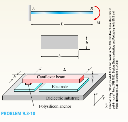
A cantilever beam model is often used to represent micro-clectrical-
Expert Solution & Answer

Trending nowThis is a popular solution!

Students have asked these similar questions
L by the double
integeration method. E = 200 GPa , I = 20 X10ʻmm“, and L = 3.0 m._Extra points will be added
if you also model it using RISA-2D software. Send me the model file, the deflected shape in a PDF file
Compute the values of slope and deflection for the beam shown below at x =
with the maximum deflection values, and a screenshot (image) for the deflection value at the pointL
shown on the deflected shape.
350 KN/m
70 KN/m
400 KN.m
Problem 6: Use element matrices potential energy formulations to solve the beam problem shown in Figure.5. Find
nodal displacement values. Make sure to construct the grid information table and one-dimensional elements'
line/mesh with appropriate labeling, numbering and displacement, loads nodal points.
Steel: E = 14(105) N/cm²
A = 20 cm?
A = 14 cm?
35500 N
ST=14°C
20000 N
a = 11(10-6)/C
85 cm
85
-70
Figure.4: Beam under axial loads
and y vs. y (phase plot)
4. Consider the deflection v of the beam to the right. The beam is supported at each end and sags due to its own
weight (a distributed load q = 50 kN/m). The equation describing the deflection is
d'u
qx (x- L)
dx
2EI
where L=5.0 m, I = 0.0052 m* and E = 1.0x10¹⁰ Pa. Use the method
of your choosing (shooting or finite differences) to solve for: 1) the
slope at each end of the beam; 2) the maximum deflection; and
3) the location of maximum deflection.
Chapter 9 Solutions
Mechanics of Materials (MindTap Course List)
Ch. 9 - The equation of the deflection curve for a...Ch. 9 - The equation of the deflection curve for a simply...Ch. 9 - -3 The deflection curve for a simple beam AB (see...Ch. 9 - The deflection curve for a simple beam AB (sec...Ch. 9 - The deflection curve for a cantilever beam AB (sec...Ch. 9 - The deflection curve for a cantilever beam AB (see...Ch. 9 - A simply supported beam is loaded with a point...Ch. 9 - A I-meter-long, simply supported copper beam (E =...Ch. 9 - A wide-flange beam (W 12 x 35) supports a uniform...Ch. 9 - A uniformly loaded, steel wide-flange beam with...
Ch. 9 - What is the span length L of a uniformly loaded,...Ch. 9 - -6 Calculate the maximum deflection of a uniformly...Ch. 9 - A cantilever beam with a uniform load (see figure)...Ch. 9 - A gold-alloy microbeam attached to a silicon wafer...Ch. 9 - Obtain a formula for the ratio c/maxof the...Ch. 9 - A cantilever beam model is often used to represent...Ch. 9 - B cams AB and CDE are connected using rigid link...Ch. 9 - -12 Derive the equation of the deflection curve...Ch. 9 - -13 Derive the equation of the deflection curve...Ch. 9 - -14 A cantilever beam AB supporting a triangularly...Ch. 9 - A cantilever beam has a length L = 12 ft and a...Ch. 9 - A simple beam with an overhang is subjected to d...Ch. 9 - -17 A cantilever beam AB is acted upon by a...Ch. 9 - -18 The beam shown in the figure has a sliding...Ch. 9 - -19 Derive the equations of the deflect ion curve...Ch. 9 - -20 Derive the equations of the deflection curve...Ch. 9 - -21 Derive the equations of the deflection curve...Ch. 9 - -22 Derive the equations of the deflection curve...Ch. 9 - -23 The beam shown in the figure has a sliding...Ch. 9 - -1 Derive the equation of the deflection curve for...Ch. 9 - -2 A simple beam AB is subjected to a distrib uted...Ch. 9 - -3 The simple beam AB shown in the figure has...Ch. 9 - -4 A beam with a uniform load has a sliding...Ch. 9 - -5 The distributed load acting on a cantilever...Ch. 9 - -6 A cantilever beam .4B is subjected to a...Ch. 9 - -7 A beam on simple supports is subjected to a...Ch. 9 - Derive the equation of the deflection curve for...Ch. 9 - -9 Derive the equations of the deflection curve...Ch. 9 - -10 Derive the equations of the deflection curve...Ch. 9 - A simply supported beam (E = 1600 ksi) is loaded...Ch. 9 - A simply supported beam (E = 12 GPa) carries a...Ch. 9 - Copper beam AB has circular cross section with a...Ch. 9 - Beam ABC is loaded by a uniform load q and point...Ch. 9 - A cantilever beam of a length L = 2.5 ft has a...Ch. 9 - A cantilever beam carries a trapezoidal...Ch. 9 - -5-7 A cantilever beam AB carries three equalaly...Ch. 9 - A simple beam AB supports five equally spaced...Ch. 9 - The cantilever beam AB shown in the figure has an...Ch. 9 - Beam ACE hangs from two springs, as shown in the...Ch. 9 - What must be the equation y =f(x) of the axis of...Ch. 9 - -12 Determine the angle of rotation Band...Ch. 9 - The cantilever beam ACE shown in the figure has...Ch. 9 - A cantilever beam is subjected to load P at...Ch. 9 - Use the method of superposition to find the angles...Ch. 9 - Repeat Problem 9,5-15 for the anti-symmetric...Ch. 9 - A cantilever beam is subjected to a quadratic...Ch. 9 - A beam ABCD consisting of a simple span BD and an...Ch. 9 - A horizontal load P acts at end C of the bracket...Ch. 9 - A beam ABC having flexural rigidity EI = 75 kN irT...Ch. 9 - Determine the angle of rotation 0Band deflectionCh. 9 - -22 A simple beam AB supports a uniform load of...Ch. 9 - The overhanging beam A BCD supports two...Ch. 9 - A thin metal strip of total weight W and length L...Ch. 9 - An overhanging beam ABC with flexural rigidity EI...Ch. 9 - A beam A BCD rests on simple supports at B and C...Ch. 9 - The compound beam ABC shown in the figure has a...Ch. 9 - A compound beam ABC DE (see figure) consists of...Ch. 9 - A steel beam ABC is simply supported at A and held...Ch. 9 - -30. Calculate the deflection at point C of a beam...Ch. 9 - Compound beam ABC is loaded by point load P = 1.5...Ch. 9 - The compound beam shown in the figure consists of...Ch. 9 - -33 Find the horizontal deflection hand verti cal...Ch. 9 - The fr a me A BCD shown in the heure is squeezed...Ch. 9 - A framework A BCD is acted on by counterclockwise...Ch. 9 - A framework A BCD is acted on by force P at 2L/3...Ch. 9 - A beam ABCDE has simple supports at B and D and...Ch. 9 - A frame ABC is loaded at point C by a force P...Ch. 9 - The wing of a large commercial jet is represented...Ch. 9 - The wing of a small plane is represented by a...Ch. 9 - Find an expression for required moment MA(in terms...Ch. 9 - Find an expression for required moment MA(in terms...Ch. 9 - Find required distance d (in terms of L) so that...Ch. 9 - A cantilever beam has two triangular loads as...Ch. 9 - -1 A cantilever beam AB is subjected to a uniform...Ch. 9 - The load on a cantilever beam AB has a triangular...Ch. 9 - A cantilever beam AB is subjected to a...Ch. 9 - Determine the angle of rotation BBand the...Ch. 9 - -5 Calen1ate the deflections S 3a ndCh. 9 - A cantileverbeam^Cßsupportstwo concentrated loads...Ch. 9 - Obtain formulas for the angle of rotation 0Aat...Ch. 9 - A simple beam AB supports two concentrated loads P...Ch. 9 - A simple beam AB is subjected to a load in the...Ch. 9 - -10 The simple beam AB shown in the figure...Ch. 9 - A simple beam AB is subjected to couples M0and 2A0...Ch. 9 - The cantilever beam ACB shown in the figure has...Ch. 9 - The cantilever beam ACB shown in the figure...Ch. 9 - Beam ACB hangs from two springs, as shown in the...Ch. 9 - -4 A simple beam ABCD has moment of inertia I near...Ch. 9 - A beam ABC has a rigid segment from A to B and a...Ch. 9 - A simple beam ABC has a moment of inertia 1,5 from...Ch. 9 - The tapered cantilever beam AB shown in the figure...Ch. 9 - The tapered cantilever beam AB shown in the figure...Ch. 9 - A tapered cantilever beam A B supports a...Ch. 9 - A tapered cantilever beam AB supports a...Ch. 9 - Repeat Problem 97-10, but now use the tapered...Ch. 9 - A simple beam ACE is constructed with square cross...Ch. 9 - A uniformly loaded simple beam AB (see figure) of...Ch. 9 - A simple beam AB of length L supports a...Ch. 9 - A propped cantilever beam AB of length L and with...Ch. 9 - A simple beam AB of length L is subjected to loads...Ch. 9 - A beam ABC with simple supports at A and B and an...Ch. 9 - A simple beam ACB supporting a uniform load q over...Ch. 9 - The frame shown in the figure consists of a beam...Ch. 9 - A simple beam AB of length L is loaded at the...Ch. 9 - The simple beam shown in the figure supports a...Ch. 9 - An overhanging beam ABC supports a concentrated...Ch. 9 - The cantilever beam shown in the figure supports a...Ch. 9 - A simple beam ACB supports a uniform load of...Ch. 9 - A cantilever beam ACB supports two concentrated...Ch. 9 - The cantilever beam A CB shown in the hgure is...Ch. 9 - The frame A BC support s a concentrated load P at...Ch. 9 - A simple beam ABC DE supports a uniform load of...Ch. 9 - An overhanging beam ABC is subjected to a couple...Ch. 9 - An overhanging beam ABC rests on a simple support...Ch. 9 - A symmetric beam A BCD with overhangs at both ends...Ch. 9 - A heavy object of weight W is dropped onto the...Ch. 9 - An object of weight Wis dropped onto the midpoint...Ch. 9 - A cantilever beam AB of length L = 6 It is...Ch. 9 - A weight W = 20 kN falls through a height h = 1,0...Ch. 9 - A weight W = 4000 lb falls through a height h =...Ch. 9 - An overhanging beam ABC with a rectangular cross...Ch. 9 - A heavy flywheel rotates at an angular speed m...Ch. 9 - A simple beam AB of length L and height /;...Ch. 9 - A cantilever beam JA of length Land height/; (see...Ch. 9 - An overhanging beam ABC of height h has a sliding...Ch. 9 - A simple beam AB of length L and height h (see...Ch. 9 - Beam AB has an elastic support kR at A, pin...
Knowledge Booster


Learn more about
Need a deep-dive on the concept behind this application? Look no further. Learn more about this topic, mechanical-engineering and related others by exploring similar questions and additional content below.Similar questions
- A simply supported I-beam is loaded with a distributed load, as shown. The deflection, y, of the center line of the beam as a function of the position, x, is given by the equation: Wo L where L=4 m is the length, E=5 GPa is the elastic modulus, I=60 x 10^(-6) m^4 is the moment of inertia, and wo=20 kN/m. Find the position x where the deflection of the beam is maximum in meters. Express your answer in meters with six decimal digits after decimal point. Wox 360LEI ... y = -(7L4 – 10L²×² + 3x*)arrow_forward3. A 3-meter-long beam is used to support a heavy object. The object has a uniform distributed load of 6 kN/m on the entire beam. The Young’s modulus and moment of inertia of the beam are 200 GPa and 5×105 mm4, respectively. The beam is supported at three positions as shown below. (a) Label the element and node numbers (either on the figure or with a new simple sketch). (b) Determine the slopes at the three support positions of the beam.arrow_forward6.5 A beam 7 m long is simply supported at its ends and loaded as follows: 120 kN at 1 m from one end A, 20 kN at 4 m from A and 60 kN at 5 m from A. Calculate the position and magnitude of the maximum deflection. The second moment of area of the beam section is 400 × 10-6 m² and E for the beam material is 210 GN/m². [9.8 mm at 3.474 m]arrow_forward
- A clamped-clamped beam having 2 elements (1) and (2), subjected to a concentrated force P at node 2, as given below. The beam has cross area (A) and young modulus (E). Fixed (1) (2) 1 L/3 3. 2L/3 a. Determine element stiffness matrix (element 1, 2) and global stiffness matrix of the beam b. Determine displace ment of node 2 at x =L/3.arrow_forward1. Figure Q1 shows a cantilever beam ABCDE subjected to a uniformly distributed load, w from points B to C. There are also a point load and a bending moment at points D and E, respectively. By using Macaulay's method; a) Develop the deflection equation in terms of w, L, E and I. Take point A as the origin. b) Given that EI = 100×106 Nm? and L = 8m, determine the value of w so that the vertical deflection at point C is 2.5 mm. c) Then, develop the slope and deflection functions if a roller support is added at point E. Take w = 600 N/m. P=: 16 W M=wL² 32 A B C E L/4 L/2 L/8 L/8 Figure Q1 [Ans: b) w = 601.44 N/m]arrow_forwardConsider a beam supported by a pin and at A and roller at B subjected to uniform distributed load w=300 N/m. If the expression of elastic curve for coordinates x1 and x2 are written as follow: V₁00=1/El [ax³+ Clx+ C2] V₂ (x)=1/El (bx4 + C3x + C4] Determine the reactions at the supports, the expressions of internal bending moments and the constants C1, C2, C3 and C4. By = M1 => M2- CL= (2- 150 downward 100 downward 100 upward 250 upward 500 downward 450 upward -50x -150 x^2 -150x -50 x -50 50 25 16.67 8.33 0 1m 100-80 50 -50 x^2 -100 x^2 -16,67 -68.7 -87.5 W 1marrow_forward
- i li. In. X O P 1:19 Upload Q1 solutions 1 Add File Q2: For the cantilever beam with uniformly distributed load shown in Figure 2. Use the data (bf,hf,bw,hw) from Table 2, determine the following: 16kN/m sm hf hw hf bw Figure 2 1. The maximum shear force in the beam in (kN) Your answer IIarrow_forwardThe cantilever beam consists of a rectangular structural steel tube shape [E = 28000 ksi; I = 530 in.4]. Use double integration to determine:(a) the beam deflection vB at point B. [ Answer: vB = -.424 in](b) the beam deflection vC at point C. [ Answer: vC = -.894 in]Assume P = 12.9 kips, w = 2.7 kips/ft, LAB = 7.0 ft, LBC = 4.3 ft.arrow_forwardHome Work: 1. Draw shear force and bending moment diagrams for the beam shown in figure. 30kN 2m 10KN/m 10m 2. Draw shear force and bending moment diagrams for the beam shown in figure. 50 kN/m 20 kN/m A B 2 m 2 m - 2 m RA Ro 3. Relation between load, shear and moment: Please solve according to the exporters of a typical solution. We will discuss the relations existing between the loads, shears and bending moments in any beam. Theses relations provide a method of constructing shea and moment diagrams without writing shear and moment equations. The beam shown in figure (1) is assumed to carry any general loading. The free body diagram wdx W (N/m) wdx of segment of this beam %3D of length (dx) is shown in figure (2). but wdx > is the summation of area between (x, and x;) RỊ R: .. V, -V, = AV = (area) jnnd similarly (1) (2) SF =0=V + wdx-(V+dV) =0 dM = w ----- Intensity of load (N/m) : dV = wd M, - M, = AM = (area ),her EM, =0= M +Vdx + (wdx) dx -(M + dM) =0 (de)? . w 3= AP Where: zero dx…arrow_forward
- For the beam and loading shown in Figure 5, determine the value of (r) at the point of action of the resuitant force of the distributed load using point B as the origin. Parabola Vertex 2000 N/m 900 N/m B 6 m A Figure 5: A parabolic distributed load on a beam AB. Answer: If the loading were analysed using point A as the origin, would the value of w at the location of the resultant change? Select one: a. No b. Yesarrow_forward20KN 2m 2m Example: (3B): Find the value of the force P to reduce the deflection of point c to the half ? 20(KNA) C B' Parrow_forwardQUESTION 3 Given the beam shown in Figure Q3, calculate the reaction at point A, consider El to be constant. Wo Deformed Shape A B Figure Q3: Beam QUESTION 4 Determine the equivalent distributed load associated with the beam shown in Figure Q4. Determine the shear, moment, slope, and deflection equations, using the Macaulay functions and the singularity functions. 400N/m 20000NM 10m 5m 5m 2000N 2000N Figure Q4; Beamarrow_forward
arrow_back_ios
SEE MORE QUESTIONS
arrow_forward_ios
Recommended textbooks for you
 Mechanics of Materials (MindTap Course List)Mechanical EngineeringISBN:9781337093347Author:Barry J. Goodno, James M. GerePublisher:Cengage Learning
Mechanics of Materials (MindTap Course List)
Mechanical Engineering
ISBN:9781337093347
Author:Barry J. Goodno, James M. Gere
Publisher:Cengage Learning
Solids: Lesson 53 - Slope and Deflection of Beams Intro; Author: Jeff Hanson;https://www.youtube.com/watch?v=I7lTq68JRmY;License: Standard YouTube License, CC-BY