
Electrical Engineering: Principles & Applications (7th Edition)
7th Edition
ISBN: 9780134484143
Author: Allan R. Hambley
Publisher: PEARSON
expand_more
expand_more
format_list_bulleted
Concept explainers
Videos
Textbook Question
Chapter 1, Problem 1.70P
The circuit shown in Figure P1.70 contains a voltage-controlled voltage source.
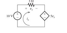
Figure P1.70
- Use KVL to write an equation relating the voltages and solve for vx.
Expert Solution & Answer
Want to see the full answer?
Check out a sample textbook solution
Students have asked these similar questions
Consider the circuit shown in Figure P1.64. Use Ohm’s law, KVL, and KCL to find V x.
Consider the circuit shown in Figure P1.68. a. Which elements are in series?b. Which elements are in parallel? c. Apply Ohm’s and Kirchhoff’s laws to solve for R x.
The circuit shown in Figure P1.70 contains a voltage-controlled voltage source. a. Use KVL to write an equation relating the voltages and solve for v x. b. Use Ohm’s law to find the current i x. c. Find the power for each element in the circuit and verify that power is conserved.
Chapter 1 Solutions
Electrical Engineering: Principles & Applications (7th Edition)
Ch. 1 - Broadly speaking, what are the two main objectives...Ch. 1 - Prob. 1.2PCh. 1 - List eight subdivisions of electrical engineering.Ch. 1 - Prob. 1.4PCh. 1 - Prob. 1.5PCh. 1 - In the fluid-flow analogy for electrical circuits,...Ch. 1 - The charge of an electron is 1.601019C . A current...Ch. 1 - The ends of a length of wire are labeled a and b....Ch. 1 - The circuit element shown in Figure P1.9 has v=12V...Ch. 1 - Prob. 1.10P
Ch. 1 - The net charge through a cross section of a...Ch. 1 - The current through a particular circuit element...Ch. 1 - The current through a given circuit element is...Ch. 1 - The net charge through a cross section of a...Ch. 1 - A copper wire has a diameter of 2.05 mm and...Ch. 1 - A certain lead acid storage battery has a mass of...Ch. 1 - A circuit element having terminals a and b has...Ch. 1 - An electron moves through a voltage of 9 V from...Ch. 1 - A typical “deep-cycle” battery (used for electric...Ch. 1 - Define the term passive reference configuration....Ch. 1 - Compute the power for each element shown in Figure...Ch. 1 - The terminals of an electrical device are labeled...Ch. 1 - The terminals of a certain battery are labeled a...Ch. 1 - The element shown in Figure P1.24 I has v(t)=10V...Ch. 1 - The current and voltage of an electrical device...Ch. 1 - Suppose that the cost of electrical energy is...Ch. 1 - Figure P1.27 shows an ammeter (AM) and voltmeter...Ch. 1 - Repeat Problem P1.27 with the meters connected as...Ch. 1 - A certain type of D-cell battery that costs $0.50...Ch. 1 - The electronics aboard a certain sailboat consume...Ch. 1 - What s a node in an electrical circuit? Identify...Ch. 1 - State Kirchhoff’s current law.Ch. 1 - Two electrical elements are connected in series....Ch. 1 - Suppose that in the fluid-flow analogy for an...Ch. 1 - Identify elements that are in series in the...Ch. 1 - Consider the circuit shown in Figure P1.36. Which...Ch. 1 - Use KCL to find the values of ia, ic , and id for...Ch. 1 - Find the values of the other currents in Figure...Ch. 1 - Prob. 1.39PCh. 1 - State Kirchhoff’s voltage law.Ch. 1 - Consider the circuit shown in Figure P1.36. Which...Ch. 1 - Use KVL to solve for the voltages va , vb, and vc...Ch. 1 - Solve for the other voltages shown in Figure P1.43...Ch. 1 - Use KVL and KCL to solve for the labeled currents...Ch. 1 - Identify elements that are in parallel in Figure...Ch. 1 - Points a, b, c, and d appear in a certain circuit....Ch. 1 - In your own words, define an ideal conductor; an...Ch. 1 - Name four types of dependent sources and give the...Ch. 1 - State Ohm’s law, including references.Ch. 1 - Draw a circuit that contains a 5 resistance, a...Ch. 1 - Repeat Problem P1.50, placing all three elements...Ch. 1 - The resistance of a certain copper wire is 0.5. ....Ch. 1 - Draw a circuit that contains a 5 resistor, a 10-V...Ch. 1 - Draw a circuit that contains a 5 resistor, a 10-V...Ch. 1 - A power of 100 W is delivered to a certain...Ch. 1 - The voltage across a 10 resistor is given by...Ch. 1 - The voltage across a 10 resistor is given by...Ch. 1 - A certain wire has a resistance of 0.5 . Find the...Ch. 1 - Plot i versus v to scale for each of the parts of...Ch. 1 - Which of the following are self-contradictory...Ch. 1 - Consider the circuit shown in Figure P1.61. Find...Ch. 1 - Consider the circuit shown in Figure P1.62. Find...Ch. 1 - Consider the circuit shown in Figure P1.63. Find...Ch. 1 - Consider the circuit shown in Figure P1.64. Use...Ch. 1 - Determine the value of Ix in the circuit shown in...Ch. 1 - Consider the circuit shown in Figure P1.66. Figure...Ch. 1 - Prob. 1.67PCh. 1 - Consider the circuit shown in Figure P1.68. Figure...Ch. 1 - Solve for the currents shown in Figure P1.69....Ch. 1 - The circuit shown in Figure P1.70 contains a...Ch. 1 - Determine the value of vx and iy in the circuit...Ch. 1 - A 10-V independent voltage source is in series...Ch. 1 - A 10-V independent voltage source is in parallel...Ch. 1 - Consider the circuit shown in Figure P1.74. Figure...Ch. 1 - The circuit shown in Figure P1.75 contains a...Ch. 1 - For the circuit shown in Figure P1.76, solve for...Ch. 1 - For the circuit shown in Figure P1.77, solve for...Ch. 1 - Match each entry in Table T1.1(a) with the best...Ch. 1 - Prob. 1.2PTCh. 1 - The circuit of Figure T1.3 has I1=3A , I2=1A ,...Ch. 1 - The circuit shown in Figure T1.4 has Vs=12V ,...Ch. 1 - We are given Vs=15V , R=10 , and =0.3S for the...Ch. 1 - We are given i4=2A for the circuit of Figure T1.6....
Additional Engineering Textbook Solutions
Find more solutions based on key concepts
Electric power systems provide energy in a variety of commercial and industrial settings. Make a list of system...
Principles and Applications of Electrical Engineering
Three point charges of equal magnitude q, that will yield a zero net electric field at the origin.
Engineering Electromagnetics
Explain the main function of each of the following major components of a PLC: a. Processor module (CPU) b. I/O ...
Programmable Logic Controllers
Design an ideal inverting op-amp circuit such that the voltage gain is Av=25 . The maximum current in any resis...
Microelectronics: Circuit Analysis and Design
What is the color code for a 365- five-band precision resistor with a tolerance of 5 percent?
ELECTRICITY FOR TRADES (LOOSELEAF)
Write the nodal equations for the network of Fig. 8.137 using the general approach. Find the nodal voltages usi...
Introductory Circuit Analysis (13th Edition)
Knowledge Booster


Learn more about
Need a deep-dive on the concept behind this application? Look no further. Learn more about this topic, electrical-engineering and related others by exploring similar questions and additional content below.Similar questions
- Use KVL to solve for the voltages v a, v b and v c in Figure P1.42arrow_forwardConsider the circuit shown in Figure P1.74. a. Use KVL to write an equation relating the voltages.b. Use Ohm’s law to write equations relating v 1 and v 2 to the current i.c. Substitute the equations from part (b) into the equation from part (a) and solve for i.d. Find the power for each element in the circuit and verify that power is conserved.arrow_forwardThe circuit below(left) displays a schematic diagram of a battery. The voltage measured by U1 is called the terminal voltage given R1 = 1 ohm. In the circuit below(right), the terminal voltage of each of the battery-resistor combination is VT = 1.5 volts. Find the voltage across R1 & voltage of the battery.arrow_forward
- Notes on the verification of ohm's law by voltage method?arrow_forwardConsider the circuit shown in Figure P1.36. a. Which elements are in parallel? b. What is the relationship between v a and v b ? c. Given that v a = 2 V and v d = -5 V determine the values of v b and v c.arrow_forwardThe circuit below(left) displays a schematic diagram of a battery. The voltage measured by U1 is called the terminal voltage given R1 = 1 ohm. In the circuit below(right), the terminal voltage of each of the battery-resistor combination is VT = 1.5 volts. Find the voltage across R1 & voltage of the battery. Find the percentage of voltage loss of the battery due to the internal resistance R1.arrow_forward
- 3. The figure on the left below shows a schematic diagram of a battery. The voltage measured by U1 is called the terminal voltage given R1 = 1 ohm. In the figure on the right below, the terminal voltage of each of the battery-resistor combination is Vr = 1.5 volts. Find the following: a. The current passing through R5. b. The currents passing through R1 and R3 C. The voltage across R1. d. The voltage of the battery EMF. e. The percentage of voltage loss ot the battery due to the internal resistance R1. The power dissipated by the internal resistance R1. g. The power dissipated by R5 if R1 = R2 = R3 = R4 = 0. h. The percentage of power dissipation loss due to the four resistors R1, R2, R3, and R4 f. R1 R3 S10 R1 U1 1.500 EMF EMF R5 100 V1 R2 $10 EMF R4 EMF EMFarrow_forwardEлample (1) For the series-parallel arrangement shown in Figure below, find: a) The supply current. I ?. b) The current flowing through each resistor. c) The p.d. across each resistor. R3 2.50 40 Ri R4 RE I ? 200Varrow_forwardUsing Kirchoff's laws, find the currents and the voltages for the figure.arrow_forward
- In the figure the ideal batteries have emfs ɛ1 = 20.4 V, ɛ2 = 9.05 V, and ɛ3 = 5.40 V, and the resistances are each 2.40 Q. What are the (a) size and (b) direction (left or right) of current i,? (c) Does battery 1 supply or absorb energy, and (d) what is its power? (e) Does battery 2 supply or absorb energy, and (f) what is its power? (g) Does battery 3 supply or absorb energy, and (h) what is its power? (a) Number i Units (b) (c) (d) Number i Units (e) (f) Number i Units (g) (h) Number i Unitsarrow_forwardTwo electrical elements are connected in series. What can you say about the currents through the elements?arrow_forwardHi please help me sketch the waveforms of voltage and current for these conditions. I ahven't understand our discussion in class pls help mearrow_forward
arrow_back_ios
SEE MORE QUESTIONS
arrow_forward_ios
Recommended textbooks for you
 Introductory Circuit Analysis (13th Edition)Electrical EngineeringISBN:9780133923605Author:Robert L. BoylestadPublisher:PEARSON
 Delmar's Standard Textbook Of ElectricityElectrical EngineeringISBN:9781337900348Author:Stephen L. HermanPublisher:Cengage Learning
 Programmable Logic ControllersElectrical EngineeringISBN:9780073373843Author:Frank D. PetruzellaPublisher:McGraw-Hill Education
 Fundamentals of Electric CircuitsElectrical EngineeringISBN:9780078028229Author:Charles K Alexander, Matthew SadikuPublisher:McGraw-Hill Education
 Electric Circuits. (11th Edition)Electrical EngineeringISBN:9780134746968Author:James W. Nilsson, Susan RiedelPublisher:PEARSON
 Engineering ElectromagneticsElectrical EngineeringISBN:9780078028151Author:Hayt, William H. (william Hart), Jr, BUCK, John A.Publisher:Mcgraw-hill Education,
Introductory Circuit Analysis (13th Edition)
Electrical Engineering
ISBN:9780133923605
Author:Robert L. Boylestad
Publisher:PEARSON
Delmar's Standard Textbook Of Electricity
Electrical Engineering
ISBN:9781337900348
Author:Stephen L. Herman
Publisher:Cengage Learning
Programmable Logic Controllers
Electrical Engineering
ISBN:9780073373843
Author:Frank D. Petruzella
Publisher:McGraw-Hill Education
Fundamentals of Electric Circuits
Electrical Engineering
ISBN:9780078028229
Author:Charles K Alexander, Matthew Sadiku
Publisher:McGraw-Hill Education
Electric Circuits. (11th Edition)
Electrical Engineering
ISBN:9780134746968
Author:James W. Nilsson, Susan Riedel
Publisher:PEARSON
Engineering Electromagnetics
Electrical Engineering
ISBN:9780078028151
Author:Hayt, William H. (william Hart), Jr, BUCK, John A.
Publisher:Mcgraw-hill Education,
Kirchhoff's Rules of Electrical Circuits; Author: Flipping Physics;https://www.youtube.com/watch?v=d0O-KUKP4nM;License: Standard YouTube License, CC-BY