
Videos
Determine the shape factor for the wide-flange beam.
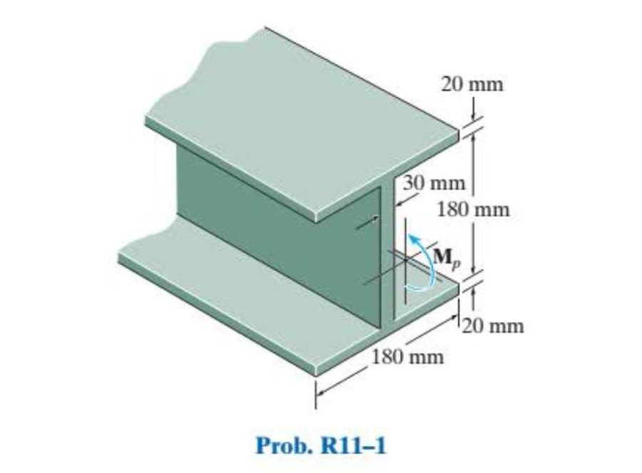
Find the shape factor for the wide-flange beam.
Answer to Problem 1RP
The shape factor for the wide-flange beam is
Explanation of Solution
Show the free-body diagram of the beam as in Figure 1.
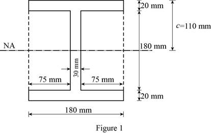
Consider the beam as rectangular and determine the moment of inertia for rectangular section and deduct the moment of inertia of the two smaller rectangular portions.
Determine the moment of inertia of the I-section using the formula.
Here, B is width of rectangular section, D is depth of large rectangular section, b is depth of small rectangular section, and d is depth of small rectangular section.
Substitute 180 mm for B, 220 mm for D, 75 mm for b, and 180 mm for d.
Determine the elastic moment using the equation.
Here,
Substitute
Show the free-body diagram of the profile view of the I-beam as in Figure 2.
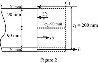
Determine the plastic moment in the I-section using the equation.
Here,
Substitute 180 mm for
Determine the shape factor for the I-section using the formula.
Substitute
Thus, the shape factor for the wide-flange beam is
Want to see more full solutions like this?
Chapter 11 Solutions
Statics and Mechanics of Materials (5th Edition)
Additional Engineering Textbook Solutions
Heating Ventilating and Air Conditioning: Analysis and Design
Vector Mechanics for Engineers: Statics
Degarmo's Materials And Processes In Manufacturing
Mechanics of Materials (10th Edition)
Machine Elements in Mechanical Design (6th Edition) (What's New in Trades & Technology)
Vector Mechanics for Engineers: Dynamics


- Use Singularity functions to draw the shear and bending moment diagram for this beam problem in terms of F and L.arrow_forwardTo calculate the necessary height of its cross-section beam of the shape, if the maximum allowed correct stress is 12MPa and the maximum allowed shear stress is 2MPa.arrow_forwardSelect the correct y for finding the bending stress at K, given that the z centroidal axis is 6 in. from the bottom of the beam. 2 in. 10 in. 14 in. K 2 in. -6 in. 6 in. -4 in. 4 in. O -5 in.arrow_forward
- Determine the reactions and draw the shear and bending moment diagrams for the beams shown by using method of consistent deformations. Select the reaction moment at the fixed support to be redundant.arrow_forwardFor the beam shown, determine the value of the EIy at midspan.arrow_forwardFind the value of the maximum deflection of each beam.arrow_forward
- What is the reaction at A?Compute the maximum bending stress in the beam. Compute the bending stress at a point on section B that is 25 mm below the top of the beam.arrow_forwardUsing singularity functions, determine the deflection in the middle of the beam.arrow_forwardDetermine the reactions and draw the shear and bending moment diagrams for the beams shown, using the method of consistent deformations. Select the reaction of the Roller support to be the redundantarrow_forward
- The cantilever beam will experience sagging bending moment when it is subjected to UDL for entire span. Select one: O True O Falsearrow_forwardThe wide-flange member is made from an elastic perfectly plastic material. Determine the shape factor for the beam.arrow_forwardas indicated below, determine the value of deflection at the right of the beamarrow_forward
 Elements Of ElectromagneticsMechanical EngineeringISBN:9780190698614Author:Sadiku, Matthew N. O.Publisher:Oxford University Press
 Mechanics of Materials (10th Edition)Mechanical EngineeringISBN:9780134319650Author:Russell C. HibbelerPublisher:PEARSON
 Thermodynamics: An Engineering ApproachMechanical EngineeringISBN:9781259822674Author:Yunus A. Cengel Dr., Michael A. BolesPublisher:McGraw-Hill Education
 Control Systems EngineeringMechanical EngineeringISBN:9781118170519Author:Norman S. NisePublisher:WILEY
 Mechanics of Materials (MindTap Course List)Mechanical EngineeringISBN:9781337093347Author:Barry J. Goodno, James M. GerePublisher:Cengage Learning
 Engineering Mechanics: StaticsMechanical EngineeringISBN:9781118807330Author:James L. Meriam, L. G. Kraige, J. N. BoltonPublisher:WILEY