
Videos
To derive: The expression for the loop gain.
Answer to Problem 12.69P
The expression for the loop gain is
Explanation of Solution
Given:
The given circuit is shown in Figure 1
Figure 1
Calculation:
The small signal equivalent diagram for the Figure is shown in Figure 2
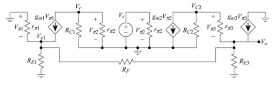
Figure 2
Apply KCL at node
Apply KCL at node
The expression for the voltage
Apply KCL at node
Substitute
Apply KCL at node
Substitute
Substitute
Substitute
Substitute
Substitute
Conclusion:
Therefore, the expression for the loop gain is
Want to see more full solutions like this?
Chapter 12 Solutions
Microelectronics: Circuit Analysis and Design


- Derive a mathematical expression to determine the stability factor for voltage – feedback bias circuit 3- S(β)arrow_forward4. The circuit uses current- (or shunt-) feedback bias. The Si transistor has ICEO = 0, VCEsat =0, and B= 100. If RC = 2k and VCC =12V, size RF for ideal maximum symmetrical swing (that is, location of the quiescent point such that VCEQ =VCC/2). +V cc RC Cc Rs RL VL Cc R. Rarrow_forwardThe open loop system transfer function is given by. Find Crossover frequency =? Gain crossover frequency=?arrow_forward
- Find the expression for the open loop gain Rm (=Output voltage/Input current). Get the expression for Ro,cl (closed loop output resistance).arrow_forward1. How does the buck converter achieve very high gain at the DC? 2. Does the Vcon (output of the voltage feedback circuit) change in line regulation? Describe the reason for your answer.arrow_forwardC. Draw a n-p-n transistor connected in circuit common emitter (CE). Draw the input current-voltage characteristic, the output current-voltage characteristics and the graph giving dependence of the output current as function of the input current. Define the amplification gain of this circuit.arrow_forward
- c) As given in the figure a clamper circuit with the input signal Vi is proposed to design. Determine the output voltage with the exact solution step by step. Sketch transfer characteristic VO versus Vi.arrow_forwardDiscuss the distinction between open-loop gain and closed-loop gain.arrow_forwarda) Obtain the open-loop transfer function. Go to page: 12 he closed-loop transfer function.. c) Find the value of gain and closed-loop poles at the imaginary axis crossing:... d) Write the range of k for which the closed system is stable.......….. e) Write the value of k that makes the system marginally stable:... f) What would be the period of oscillation. g) Find %OS, Tp, Ts, atk = 15. h) Find the steady-state errors when the input is r(t)= 0.62 u(t) step at k=15:.. H(s)G(s): k (s + 7)(s +1-j)(s +1+j)arrow_forward
- Draw a n-p-n transistor connected in circuit common base (CB).Draw the input current-voltage characteristic, the output current-voltage characteristicsand the graph giving dependence of the output current as function of the input current.Define the amplification gain of this circuit.arrow_forwardConsider the block diagram in Figure CP2.6.(a) Use an m-file to reduce the block diagram inFigure CP2.6, and compute the closed-loop transfer function. (b) Generate a pole–zero map of the closed-looptransfer function in graphical form using thepzmap function.(c) Determine explicitly the poles and zeros of theclosed-loop transfer function using the pole andzero functions and correlate the results with thepole–zero map in part (b).arrow_forward(A): Convert the Block Diagram showing in figure (2) to a Signal-Flow Graph (SFG). (B): Reduce the block diagram shown in figure (2) to a single transfer function Y(s)/R(s). (C): For the close loop system, find the values of damping ratio (), natural frequency (wn), percent overshoot (%OS), Peak time (Tp), Rise time (Tr), and settling time (Ts) Y(s) 2500 %3D R(s) s2 + 50 s + 2500 R(s) Y(s) 1 1 K s+0.4 2+1.7s+0.25 G1(s) G2(s) G3(s) Figure (1) 0.1 s+0.1 H(s) R(s) V1(s) V2(s) G1(s) V4(s) V5(s) Y(s) G3(s) G4(s) V3(s) Figure (2) G2(s) V6(s) H(s)arrow_forward
 Introductory Circuit Analysis (13th Edition)Electrical EngineeringISBN:9780133923605Author:Robert L. BoylestadPublisher:PEARSON
 Delmar's Standard Textbook Of ElectricityElectrical EngineeringISBN:9781337900348Author:Stephen L. HermanPublisher:Cengage Learning
 Programmable Logic ControllersElectrical EngineeringISBN:9780073373843Author:Frank D. PetruzellaPublisher:McGraw-Hill Education
 Fundamentals of Electric CircuitsElectrical EngineeringISBN:9780078028229Author:Charles K Alexander, Matthew SadikuPublisher:McGraw-Hill Education
 Electric Circuits. (11th Edition)Electrical EngineeringISBN:9780134746968Author:James W. Nilsson, Susan RiedelPublisher:PEARSON
 Engineering ElectromagneticsElectrical EngineeringISBN:9780078028151Author:Hayt, William H. (william Hart), Jr, BUCK, John A.Publisher:Mcgraw-hill Education,