
Mechanics of Materials
11th Edition
ISBN: 9780137605460
Author: Russell C. Hibbeler
Publisher: Pearson Education (US)
expand_more
expand_more
format_list_bulleted
Concept explainers
Videos
Textbook Question
thumb_up100%
Chapter 1.2, Problem 1FP
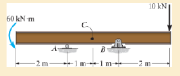
Determine the resultant internal normal force, shear force, and bending moment at point C in the beam.
Expert Solution & Answer

Learn your wayIncludes step-by-step video

schedule03:21
Students have asked these similar questions
Determine the resultant internal normal force, shear force, and bending moment at point C in the beam.
Determine the bending moment M in the beam at the point located L = 4.05 m to the left of point C. The ground reactions and shear-force diagram are shown.
Determine the bending moment M in the beam at the point located 0.44 m to the right of point B. The ground reactions and shear-force diagram are shown.
Chapter 1 Solutions
Mechanics of Materials
Ch. 1.2 - Determine the resultant internal normal force,...Ch. 1.2 - Determine the resultant internal normal force,...Ch. 1.2 - Determine the resultant internal normal force,...Ch. 1.2 - Determine the resultant internal normal force,...Ch. 1.2 - Determine the resultant internal normal force,...Ch. 1.2 - Determine the resultant internal normal force,...Ch. 1.2 - The shaft is supported by a smooth thrust bearing...Ch. 1.2 - Determine the resultant internal normal and shear...Ch. 1.2 - Determine the resultant internal torque acting on...Ch. 1.2 - Determine the resultant internal loadings in the...
Ch. 1.2 - The shaft is supported by a smooth thrust bearing...Ch. 1.2 - Determine the resultant internal loading on the...Ch. 1.2 - Determine the resultant internal loading on the...Ch. 1.2 - The 800-lb load is being hoisted at a constant...Ch. 1.2 - Determine resultant internal loadings acting on...Ch. 1.2 - Determine the resultant internal normal force...Ch. 1.2 - Determine the resultant internal loadings on the...Ch. 1.2 - Determine the resultant internal loadings on the...Ch. 1.2 - The blade of the hacksaw is subjected to a...Ch. 1.2 - The blade of the hacksaw is subjected to a...Ch. 1.2 - Determine the resultant internal loadings on the...Ch. 1.2 - Determine the resultant internal loadings on the...Ch. 1.2 - The sky hook is used to support the cable of a...Ch. 1.2 - Determine the resultant internal torque acting on...Ch. 1.2 - Determine the resultant internal loadings acting...Ch. 1.2 - Determine the resultant internal loadings on the...Ch. 1.2 - Determine the resultant internal loadings on the...Ch. 1.2 - The metal stud punch is subjected to a force of...Ch. 1.2 - The metal stud punch is subjected to a force of...Ch. 1.2 - Determine the resultant internal loadings acting...Ch. 1.2 - A force of 80 N is supported by the bracket....Ch. 1.2 - The curved rod has a radius r and is fixed to the...Ch. 1.2 - The pipe assembly is subjected to a force of 600 N...Ch. 1.2 - If the drill bit jams when the handle of the hand...Ch. 1.2 - The curved rod AD of radius r has a weight per...Ch. 1.2 - A differential element taken from a curved bar is...Ch. 1.5 - The uniform beam is supported by two rods AB and...Ch. 1.5 - Determine the average normal stress on the cross...Ch. 1.5 - Determine the average normal stress on the cross...Ch. 1.5 - If the 600-kN force acts through the centroid of...Ch. 1.5 - Determine the average normal stress at points A,...Ch. 1.5 - Determine the average normal stress in rod AB if...Ch. 1.5 - A 175-lb woman stands on a vinyl floor wearing...Ch. 1.5 - Determine the largest intensity w of the uniform...Ch. 1.5 - The specimen failed in a tension test at an angle...Ch. 1.5 - The built-up shaft consists of a pipe AB and solid...Ch. 1.5 - If the material fails when the average normal...Ch. 1.5 - If the block is subjected to a centrally applied...Ch. 1.5 - The plate has a width of 0.5 m. If the stress...Ch. 1.5 - The member is subjected to a tensile force of 200...Ch. 1.5 - The boom has a uniform weight of 600 lb and is...Ch. 1.5 - Determine the average normal stress in each of the...Ch. 1.5 - If the average normal stress in each of the...Ch. 1.5 - Determine the maximum average shear stress in pin...Ch. 1.5 - The 150-kg bucket is suspended from end E of the...Ch. 1.5 - The 150-kg bucket is suspended from end E of the...Ch. 1.5 - If the pedestal is subjected to a compressive...Ch. 1.5 - The beam is supported by two rods AB and CD that...Ch. 1.5 - The beam is supported by two rods AB and CD that...Ch. 1.5 - The beam is supported by a pin at B and a short...Ch. 1.5 - The railcar docklight is supported by the...Ch. 1.5 - The plastic block is subjected to an axial...Ch. 1.5 - During a tension test, the wooden specimen is...Ch. 1.5 - The bar has a cross-sectional area of 400(106) m2....Ch. 1.5 - The bar has a cross-sectional area of 400(106) m2....Ch. 1.5 - Prob. 54PCh. 1.5 - The 2-Mg concrete pipe has a center of mass at...Ch. 1.5 - The 2-Mg concrete pipe has a center of mass at...Ch. 1.5 - The pier is made of material having a specific...Ch. 1.5 - Prob. 58PCh. 1.5 - The uniform bar, having a cross-sectional area of...Ch. 1.5 - Prob. 60PCh. 1.5 - Prob. 61PCh. 1.5 - The triangular blocks are glued along each side of...Ch. 1.5 - The triangular blocks are glued along each side of...Ch. 1.5 - Prob. 64PCh. 1.5 - Determine the maximum magnitude P of the load the...Ch. 1.5 - Prob. 66PCh. 1.5 - Prob. 67PCh. 1.7 - Rods AC and BC are used to suspend the 200-kg...Ch. 1.7 - If it is subjected to double shear, determine the...Ch. 1.7 - Determine the maximum average shear stress...Ch. 1.7 - If each of the three nails has a diameter of 4 mm...Ch. 1.7 - The strut is glued to the horizontal member at...Ch. 1.7 - Determine the maximum average shear stress...Ch. 1.7 - If the eyebolt is made of a material having a...Ch. 1.7 - If the bar assembly is made of a material having a...Ch. 1.7 - Determine the maximum force P that can be applied...Ch. 1.7 - The pin is made of a material having a failure...Ch. 1.7 - If the bolt head and the supporting bracket are...Ch. 1.7 - Six nails are used to hold the hanger at A against...Ch. 1.7 - If A and B are both made of wood and are 38 in....Ch. 1.7 - Prob. 70PCh. 1.7 - The connection is made using a bolt and nut and...Ch. 1.7 - Determine the required cross-sectional area of...Ch. 1.7 - Prob. 73PCh. 1.7 - The spring mechanism is used as a shock absorber...Ch. 1.7 - Prob. 75PCh. 1.7 - The hangers support the joist in such a way that...Ch. 1.7 - Prob. 77PCh. 1.7 - Prob. 78PCh. 1.7 - The two aluminum rods AB and BC have diameters of...Ch. 1.7 - The cotter is used to hold the two rods together....Ch. 1.7 - Prob. 81PCh. 1.7 - The 60mm60mm oak post is supported on the pine...Ch. 1.7 - Prob. 83PCh. 1.7 - Prob. 84PCh. 1.7 - The assembly consists of three disks A, B, and C...Ch. 1.7 - Prob. 86PCh. 1.7 - Prob. 87PCh. 1.7 - Prob. 88PCh. 1.7 - Prob. 89PCh. 1.7 - Prob. 90PCh. 1.7 - Prob. 91PCh. 1.7 - Prob. 92PCh. 1.7 - Prob. 93PCh. 1.7 - The aluminum bracket A is used to support the...Ch. 1.7 - If the allowable tensile stress for the bar is...Ch. 1.7 - The bar is connected to the support using a pin...Ch. 1 - The beam AB is pin supported at A and supported by...Ch. 1 - The long bolt passes through the 30-mm-thick...Ch. 1 - Determine the required thickness of member BC to...Ch. 1 - The circular punch B exerts a force of 2 kN on the...Ch. 1 - Determine the average punching shear stress the...Ch. 1 - The 150 mm by 150 mm block of aluminum supports a...Ch. 1 - The yoke-and-rod connection is subjected to a...Ch. 1 - The cable has a specific weight (weight/volume)...
Additional Engineering Textbook Solutions
Find more solutions based on key concepts
4.44 Compute reactions at each support for the beam shown. The beam weight is 50 lb/ft.
Applied Statics and Strength of Materials (6th Edition)
Determine the resultant internal loadings acting on the cross sections at points F and G of the frame. Probs. 7...
Statics and Mechanics of Materials (5th Edition)
Determine the horizontal and vertical components of force which the pins at A and B exert on the frame. Prob. 6...
INTERNATIONAL EDITION---Engineering Mechanics: Statics, 14th edition (SI unit)
The forces developed in each cable for equilibrium.
Engineering Mechanics: Statics & Dynamics (14th Edition)
Convert a volume flow rate of 3.0 gal/min to rrP/s.
Applied Fluid Mechanics (7th Edition)
State whether the members are in tension or compression. Set P = 8 kN. Probs. 6-16/17
Engineering Mechanics: Statics
Knowledge Booster


Learn more about
Need a deep-dive on the concept behind this application? Look no further. Learn more about this topic, mechanical-engineering and related others by exploring similar questions and additional content below.Similar questions
- 1. Determine the internal normal force, shear force, and bending moment at point C in the beam. 300 Ib/ft B -3 ft -3 ft-arrow_forwardDetermine the internal normal force and shear force, and the bending moment in the beam at points C and D. Assume the support at B is a roller. Point C is located just to the right of the 8-kip load.arrow_forwardGive the expression for the shear force, V = V(x), and the bending moment,M = M(x), as a function of the distance, x, measured from point A.Hint: Find the expressions of shear force and bending moment in each section:AB (0< x <4), BC (4 <x <7) and CD (7< x <10)arrow_forward
- Determine the ff: •Internal bending moment at point c •internal shear force at point c •internal normal force at point c Asap please.arrow_forwardDetermine the normal force, shear force, and moment at points C and D in the beam.arrow_forwardDetermine the normal force, shear force, and moment at point C. Assume A is pinned and B is a roller. Take that w = 4.2 kN/m Determine the shear force at point C. Determine the moment at point C.arrow_forward
- Determine the maximum shear force and maximum bending moment for the beam.arrow_forwardQ 1/ Draw the shear-force and bending-moment diagrams for the beam shown using the graphical method. Determine the maximum negative moment. Derive equations for the shear force V and the bending moment M for any location in the beam. 50 kN 40 kN/m 60 kN-m B 3m Imarrow_forwardDetermine the internal shear force and moment acting on point C 7-8. Determine the internal shear force and moment acting at point C in the beam. 900 lb-ft -3 ft- 6 ft Vc = 0 Mc = 8100 lb*ft 500 lb/ft + Prob. 7-8 6 ft B 900 lb-ft -3 ft-arrow_forward
- Use the graphical method to construct the shear-force and bending-moment diagrams for the beam shown. Label all significant points on each diagram and identify the maximum moments along with their respective locations. Additionally: (a) Determine V and M in the beam at a point located 1.50 m to the right of B. (b) Determine V and M in the beam at a point located 1.25 m to the left of D. Let a = 3.1 m, b = 5.9 m, w = 34 kN/m, P = 48 kN, Q = 34 kN, and Mc = 155 kN-m. Construct the shear-force and bending-moment diagram P w A B E Mc a a aarrow_forwardDetermine the magnitude of the resultant internal normal force, shear force and bending moment on the cross section at point Darrow_forwardDetermine the internal normal force N, shear force V and moment M at point D in the beam as shownarrow_forward
arrow_back_ios
SEE MORE QUESTIONS
arrow_forward_ios
Recommended textbooks for you
 Elements Of ElectromagneticsMechanical EngineeringISBN:9780190698614Author:Sadiku, Matthew N. O.Publisher:Oxford University Press
 Mechanics of Materials (10th Edition)Mechanical EngineeringISBN:9780134319650Author:Russell C. HibbelerPublisher:PEARSON
 Thermodynamics: An Engineering ApproachMechanical EngineeringISBN:9781259822674Author:Yunus A. Cengel Dr., Michael A. BolesPublisher:McGraw-Hill Education
 Control Systems EngineeringMechanical EngineeringISBN:9781118170519Author:Norman S. NisePublisher:WILEY
 Mechanics of Materials (MindTap Course List)Mechanical EngineeringISBN:9781337093347Author:Barry J. Goodno, James M. GerePublisher:Cengage Learning
 Engineering Mechanics: StaticsMechanical EngineeringISBN:9781118807330Author:James L. Meriam, L. G. Kraige, J. N. BoltonPublisher:WILEY
Elements Of Electromagnetics
Mechanical Engineering
ISBN:9780190698614
Author:Sadiku, Matthew N. O.
Publisher:Oxford University Press
Mechanics of Materials (10th Edition)
Mechanical Engineering
ISBN:9780134319650
Author:Russell C. Hibbeler
Publisher:PEARSON
Thermodynamics: An Engineering Approach
Mechanical Engineering
ISBN:9781259822674
Author:Yunus A. Cengel Dr., Michael A. Boles
Publisher:McGraw-Hill Education
Control Systems Engineering
Mechanical Engineering
ISBN:9781118170519
Author:Norman S. Nise
Publisher:WILEY
Mechanics of Materials (MindTap Course List)
Mechanical Engineering
ISBN:9781337093347
Author:Barry J. Goodno, James M. Gere
Publisher:Cengage Learning
Engineering Mechanics: Statics
Mechanical Engineering
ISBN:9781118807330
Author:James L. Meriam, L. G. Kraige, J. N. Bolton
Publisher:WILEY
Understanding Shear Force and Bending Moment Diagrams; Author: The Efficient Engineer;https://www.youtube.com/watch?v=C-FEVzI8oe8;License: Standard YouTube License, CC-BY
Bending Stress; Author: moodlemech;https://www.youtube.com/watch?v=9QIqewkE6xM;License: Standard Youtube License