
Videos
The overall small-signal voltage gain of the amplifier.
Answer to Problem 13.20P
The overall small-signal voltage gain of the amplifier is
Explanation of Solution
Given:
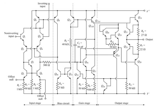
Consider the 741 op-amp having bias voltage ±5 V
Calculation:
The reference current is.
Current
The bias currents in the input stage are,
The voltage at the collector of
The collector current in
Now, current
Assuming
The current in
The input resistance to the gain stage is found as
Therefore, the emitter resistor
Also
Consequently, the resistor value
Now the resistance of the active load is determined as
And
Then
Now the resistance
The small signal differential voltage is
The effective resistance of the active load is the resistance looking into the collector of
The small signal voltage gain is
The overall gain is
Want to see more full solutions like this?
Chapter 13 Solutions
Microelectronics: Circuit Analysis and Design


- Figure below shows a circuit for a pulse width modulator (PWM) amplifier. I. Describe how the circuit achieves low power dissipation 2. Describe with the aid of drawings the signal waveform shapes at points, A, B and Carrow_forwardWith an aid of a. c. equivalent circuit, derive an equation representing common- mode gain (Ac) of the circuit.arrow_forward4) Consider the clamping circuit below, assume Vref=3 V and Vin=5sin(wt) ..Draw the output voltage waveform. Clearly mark the max and min of the voltage.. Vrefarrow_forward
- The small-signal model is said to be valid for voltage variations of about 5 mV. To what percentage current change does this correspond? (Consider both positive and negative signals.) What is the maximum allowable voltage signal (positive or negative) if the current change is to be limited to 10%?arrow_forwardFind the following: DC gain, inductor current ripple and output voltage ripple: For DC-DC Buck converter: 1-Draw all circuits in all position 2-Sketch the transistor current waveform 3-Derive analytical expressions for the dc components of the capacitor voltages and inductor currents. 4-Derive analytical expressions for the peak ripple magnitudes of the input filter inductor current and capacitor voltage.arrow_forward(ii) What is IEEE519 standard? Explain the significance of the terms PCC, Isc and I used in this standard. Describe the maximum harmonics current distortion in % of I for individual harmonic order prescribed by this standard.arrow_forward
- circuits by using the small signal models of the transistor. Assume the Early voltage of the transistors are infinitely large. Calculate the small-signal input and output impedances of the following Vcc R1 R1 Rout VB RE Rin R2arrow_forwardIn the circuit shown in the figure, the internal resistance of a voltage source is given as 3 ohms. Load values are such that R = 20 ohms and X = 20 ohms. The effective value of the VAB voltage at the load ends is 220 V. (Frequency is 50 Hz). What is the active power consumed by the load? (Do not take into account 3 ohms in calculations)arrow_forwardFor the MOSFET shown in Figure Q2d, VGs (off) = -6V, IDss = 10.5 mA and Vps = 11V. Determine, d) i) What is the type of MOSFET and the amplifier configuration? ii) What is the value of the drain resistance, Rp? 15V VDD RD Q1 LRG 9MO Figure Q2darrow_forward
- PLEASE NEED NOW For the amplifier circuit of the Figure shown below, calculate the voltage gain of each stage, the overall amplifier voltage gain and the output voltage.arrow_forwardIn a full-bridge dc-dc converter using PWM bipolar voltage switching, analytically obtain the value of (V/V) which results in the maximum (peak-peak) ripple in the output current i,. Calculate this ripple in terms of Va, La, and farrow_forwardConsider a buck converter with the controlled switch as MOSFET and the uncontrolled switch as diode, the input to buck converter is 60 V. The MOSFET is turned on and off for 20 msec and 10 msec periodically. Assuming ideal components, the output voltage of the buck converter isarrow_forward
 Introductory Circuit Analysis (13th Edition)Electrical EngineeringISBN:9780133923605Author:Robert L. BoylestadPublisher:PEARSON
 Delmar's Standard Textbook Of ElectricityElectrical EngineeringISBN:9781337900348Author:Stephen L. HermanPublisher:Cengage Learning
 Programmable Logic ControllersElectrical EngineeringISBN:9780073373843Author:Frank D. PetruzellaPublisher:McGraw-Hill Education
 Fundamentals of Electric CircuitsElectrical EngineeringISBN:9780078028229Author:Charles K Alexander, Matthew SadikuPublisher:McGraw-Hill Education
 Electric Circuits. (11th Edition)Electrical EngineeringISBN:9780134746968Author:James W. Nilsson, Susan RiedelPublisher:PEARSON
 Engineering ElectromagneticsElectrical EngineeringISBN:9780078028151Author:Hayt, William H. (william Hart), Jr, BUCK, John A.Publisher:Mcgraw-hill Education,