
Concept explainers
Videos
(a)
The total power dissipated by the ideal source.
Answer to Problem 2.31HP
The power delivered for the current of
Explanation of Solution
Calculation:
The formula for the total power supplied or delivered by the ideal voltage source is given by,
Substitute
Substitute
Substitute
Substitute
Substitute
Substitute
Substitute
Conclusion:
Therefore, the power delivered for the current of
(b)
The power dissipated within the non ideal source.
Answer to Problem 2.31HP
The power dissipated by the resistance of
Explanation of Solution
Calculation:
The formula for the power delivered by the non ideal power source is given by,
Substitute
Substitute
Substitute
Substitute
Substitute
Substitute
Conclusion:
Therefore, the power dissipated by the resistance of
(c)
The amount of power supplied by the load resistor.
Answer to Problem 2.31HP
The power supplied to the load resistance of
Explanation of Solution
Calculation:
The given diagram is shown in Figure 1
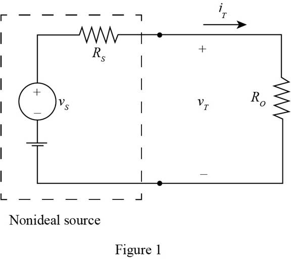
Apply KCL to the above circuit.
The formula for the load power is given by,
The conversion of
The conversion of
The conversion of
The conversion of
The conversion of
The conversion of
Substitute
Substitute
Substitute
Substitute
Substitute
Substitute
Substitute
Substitute
Substitute
Substitute
Substitute
Substitute
Conclusion:
Therefore, the power supplied to the load resistance of
(d)
The terminal voltage
Answer to Problem 2.31HP
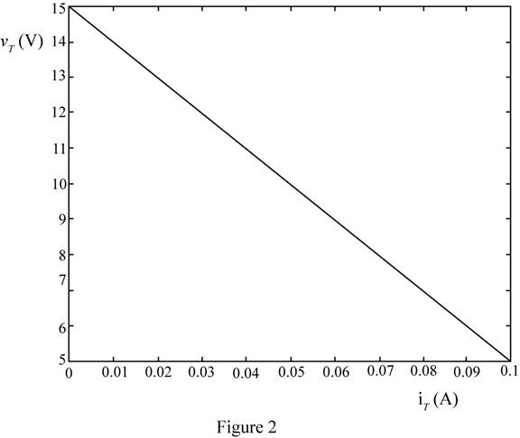
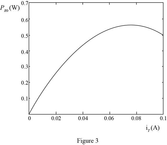
The plot between the terminal voltage and the load current is shown in Figure 2 and plot for the load current and power delivered to the load is shown in Figure 3
Explanation of Solution
Calculation:
The plot for the terminal voltage and total current is shown in Figure 2.
The plot between for the power delivered to the load versus the total current is shown in Figure 3
Conclusion:
Therefore, the plot between the terminal voltage and the load current is shown in Figure 2 and plot for the load current and power delivered to the load is shown in Figure 3
Want to see more full solutions like this?
Chapter 2 Solutions
Principles and Applications of Electrical Engineering


- In the circuit in the figure, the value of the current I1 is found as ………..Amperes.arrow_forwardFor the series-parallel arrangement shown in the Figure below, find (a) the supply current, (b) the current flowing through each resistor and (c) the p.d. across each resistor (d). power dissipated by each resistor.arrow_forwardIn the figure is shown a battery having an emf of 12 Volts and an internal resistance of 0.40 Ohm.A resistor R1 of 2.6 Ohms is connected across itsterminals ab. Determine (a) resistance of Rwhich, when connected across terminals ab inparallel with R1 will make the powerdelivered by the battery a maximum; (b)current in R1 and R; (c) terminal voltage ofbattery; (d) power in R1 and in R; (e) power lost in batteryHint: To maximize power in R, use differentiation In the circuit shown, a 6-Ohm resistor connected in series to a parallel combination of tworesistors, one is 30-Ohm and the other is R beingunknown. Determine the value of R if: (a) thepower dissipated in 6-Ohm resistor is equal tothe power in the parallel combination; (b) hepower in 6-Ohm is equal to the power of in R; (c)value of R maximum power transfer.Hint: To maximize power in R, use differentiationarrow_forward
- Differentiate between Kirchhoff's Voltage Law and Kirchhoff's Current Law. Support you answer by appropriate example. Debate that how these laws are supportive to solve complex circuits.arrow_forwardThe circuit below(left) displays a schematic diagram of a battery. The voltage measured by U1 is called the terminal voltage given R1 = 1 ohm. In the circuit below(right), the terminal voltage of each of the battery-resistor combination is VT = 1.5 volts. Find The percentage of power dissipation loss due to the four resistors R1, R2, R3, and R4.arrow_forwardroblem 2. (a) Find the equivalent resistance between point a and point b in figure below. (b) If the potential drop between point and point b is 12.0 V, find the current in the 12.0 resistor.arrow_forward
- In the circuit in Figure 2, the capacitor andThe circuit of resistance is defined as a load circuit.a) Find the average power dissipated by the load circuit?b) How much of the average power calculated in a) by the resistance in the load circuit and how muchspent by the capacitor? Interpreting the results obtained?c) In the circuit in Figure 2, with a resistance of 80 ohms 23?A coil of is connected in series. In this case,calculating transformer ratio () to optimize power delivery to the load? Obtainedinterpreting the result?d) Calculate the distributed load complex power and reactive power in the newly learned circuit?arrow_forwardQ2 (a) () What is the difference between a Wheatstone bridge and a Kelvin bridge? Your explanation should include suitable diagrams and applications. (ii) Figure Q2a(ii) shows an AC bridge and the meter indicates zero reading. Find the equation for R, from the real part of the impedance Figure Q2a(1) (i) Given that the value for the resistors R. R. R. are 100 02, 250 £2 and 300 1, respectively. The capacitors C, and Care 1 uF and 0.5 µF, respectively. Calculate the resistor. Rarrow_forwardThe circuit below(left) displays a schematic diagram of a battery. The voltage measured by U1 is called the terminal voltage given R1 = 1 ohm. In the circuit below(right), the terminal voltage of each of the battery-resistor combination is VT = 1.5 volts. Find The power dissipated by the internal resistance R1. The power dissipated by R5 if R1 = R2 = R3 = R4 = 0arrow_forward
- b-Two aluminum and copper wire resistors consume 0.5 W when connected in parallel to 2 V DC supply. The aluminum wire is 40% length more than copper wire. Calculate the power consumed by the two resistors when connected in series to the same DC supply. Assume equal cross-section area and the resistivity of aluminum is to be 20% more than that of copper.arrow_forwardConsider the circuit shown in the figure below. (Let R₁ = 6.00 0, R₂ = 8.00 0, and 8 - 10.0 V.) 2.000 W 10.00 www 5.000 www & 16 (a) Find the voltage across R₁. (b) Find the current in R₁. R₂ wwwarrow_forwardThe diagram shows an ideal (zero internal resistance) DC source connected to three identical resitances and a switch. In the diagram, the switch is open. If initially, the switch is open, what happens to current I1 and I2 after the switch is closed?arrow_forward
 Introductory Circuit Analysis (13th Edition)Electrical EngineeringISBN:9780133923605Author:Robert L. BoylestadPublisher:PEARSON
 Delmar's Standard Textbook Of ElectricityElectrical EngineeringISBN:9781337900348Author:Stephen L. HermanPublisher:Cengage Learning
 Programmable Logic ControllersElectrical EngineeringISBN:9780073373843Author:Frank D. PetruzellaPublisher:McGraw-Hill Education
 Fundamentals of Electric CircuitsElectrical EngineeringISBN:9780078028229Author:Charles K Alexander, Matthew SadikuPublisher:McGraw-Hill Education
 Electric Circuits. (11th Edition)Electrical EngineeringISBN:9780134746968Author:James W. Nilsson, Susan RiedelPublisher:PEARSON
 Engineering ElectromagneticsElectrical EngineeringISBN:9780078028151Author:Hayt, William H. (william Hart), Jr, BUCK, John A.Publisher:Mcgraw-hill Education,