
Videos
(a)
The diagram of the circuit.
(a)
Answer to Problem 83P
The diagram is shown in figure (1).
Explanation of Solution
Calculation:
The diagram of the electric circuit is shown below,
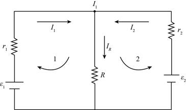
Figure (1)
Conclusion:
Therefore, the diagram is shown in figure (1).
(b)
The current in each branch of the circuit.
(b)
Answer to Problem 83P
The current
Explanation of Solution
Formula used:
The expression for Kirchhoff’s law in first loop is given by,
The expression for Kirchhoff’s law in second loop is given by,
The expression for current in loop 1 is given by,
Calculation:
The expression for Kirchhoff’s law in first loop is calculated as,
The expression for Kirchhoff’s law in second loop is calculated as,
From equation (1) and (2),
Substitute
The
Conclusion:
Therefore, the current
(c)
The power supplied by second battery.
(c)
Answer to Problem 83P
The power supplied by second battery is
Explanation of Solution
Formula used:
The expression for power received by first battery is given by,
The expression for power received by second battery is given by,
The expression for power dissipated in load resistance is given by,
Calculation:
The expression for power received by first battery is calculated as,
The expression for power received by second battery is calculated as,
The power dissipated in load resistance is calculated as,
Conclusion:
Therefore, the power supplied by second battery is
Want to see more full solutions like this?
Chapter 25 Solutions
Physics for Scientists and Engineers


- The values of the components in a simple series RC circuit containing a switch (Fig. P21.53) are C = 1.00 F, R = 2.00 106 , and = 10.0 V. At the instant 10.0 s after the switch is closed, calculate (a) the charge on the capacitor, (b) the current in the resistor, (c) the rate at which energy is being stored in the capacitor, and (d) the rate at which energy is being delivered by the battery.arrow_forwardYou connect a 10.0 MΩ resistor in series with a 3.20 mFcapacitor and a battery with emf 9.00 V. Before you close the switchat t = 0 to complete the circuit, the capacitor is uncharged. Find the fraction of the final charge on the capacitor at t = 18.0 sarrow_forwardA heart defibrillator being used on a patient has an RC time constant of 9.5 ms due to the resistance of the patient's body and the capacitance of the defibrillator. τ = 9.5 msC = 6.5 μFV = 11.5 kV a) If the defibrillator has an 6.5 μF capacitance, what is the resistance of the path through the patient in kΩ? b) If the initial voltage is 11.5 kV, how long does it take to decline to 6.00 × 10² V in ms?arrow_forward
- In the figure R1 = R2 = 10.22 0, and the ideal battery has emf g = 12.08 V. (a) What value of R3 maximizes the rate at which the battery supplies energy and (b) what is that maximum rate? R1 R (a) Number Units Units (b) Numberarrow_forwardYou connect a battery, resistor, and capacitor as in the figure, where R = 16.0 Ω and C = 8.00 ×10⁻⁶ F. The switch S is closed at t = 0. When the current in the circuit has magnitude 3.00 A, the charge on the capacitor is 40.0 × 10⁻⁶ C. (a) What is the emf of the battery? (b) At what time t after the switch is closed is the charge on the capacitor equal to 40.0×10⁻⁶ C? (c) When the current has magnitude 3.00 A, at what rate is energy being stored in the capacitor? (d) When the current has magnitude 3.00 A, at what rate is energy being supplied by the battery?arrow_forwardYour toaster has a power cord with a resistance of 0.020 Ω connected in series with a 9.6@Ω nichrome heating element. If thepotential difference between the terminals of the toaster is 120 V,how much power is dissipated in (a) the power cord and (b) theheating element?arrow_forward
- You connect a 10.0 MΩ resistor in series with a 3.20 mFcapacitor and a battery with emf 9.00 V. Before you close the switchat t = 0 to complete the circuit, the capacitor is uncharged. Find the final capacitor chargearrow_forwardRes-monster maze. In the figure, all the resistors have a resistance of 4.0 2 and all the (ideal) batteries have an emf of 4.0 V. What is the current through resistor R? (If you can find the proper loop through this maze, you can answer the question with a few seconds of mental calculation.) O 4 A O 2 A O 1 A O 0.5 A wtwHarrow_forwardOccupational safety experts have developed an alternative criterion for electrical safety. They have found that shocks lasting less than 3 s will be nonlethal if the product of the voltage drop across the body, the current through the body, and the time ( ≤ 3.0 s) that the current flows does not exceed 13.5 V • A • s = 13.5 J . Suppose that one hand of a potential victim is grounded and the other hand touches a voltage source; suppose further that his skin resistance is negligible—a worstcase scenario. Using the criterion above, what is the lowest voltage that will not be lethal for a shock that lasts 1.0 s?arrow_forward
- In the figure ε1 = 2.45 V, ε2 = 0.803 V, R1 = 6.98 Ω, R2 = 1.53 Ω, R3 = 5.09 Ω, and both batteries are ideal. (a) What is the rate at which energy is dissipated in R1, R2, and R3? (b) What is the power of battery 1 and battery 2?arrow_forwardPatients with recurring ventricular arrhythmia, irregular beats of the heart's ventricles, are often fitted with implantable cardioverter defibrillators (ICD) that monitor the beating of the patient's heart. Much like an external defibrillator, an ICD delivers up to 40.0 J of energy to the heart when irregular heartbeat is detected. A standard ICD contains a 3.2 V lithium ion battery and has an equivalent capacitance of 140 µF. (a) What is the charge (in C) stored on the fully charged capacitor in an ICD? 0.106 с (b) What should the internal resistance (in 2) of the charging circuit in the ICD be if the capacitor is to attain 94.9% of its maximum charge within 1.75 s? -4200 X How does the charge of a capacitor increase as it is being charged? What is the desired percentage of the total charge after the time interval specified in the problem? (c) The total effective resistance of the circuit when the ICD discharges through the heart is 500 , in series with the capacitor in the ICD.…arrow_forward· (a) In the figure, determine the potential difference Vad. (b) If a battery with emf 9.30 V and internal resistance of 1.00 ohm is inserted in the circuit at d, with its negative terminal connected to the negative terminal of the 8.00- V battery. What is now the potential difference Vbc? 0.50 2 4.00 V 9.00 N 6.00 Ω 0.50 N 8.00 V ww 8.00 Ωarrow_forward
 Principles of Physics: A Calculus-Based TextPhysicsISBN:9781133104261Author:Raymond A. Serway, John W. JewettPublisher:Cengage Learning