
Concept explainers
Videos
3–1* to 3–4 Sketch a free-body diagram of each element in the figure. Compute the magnitude and direction of each force using an algebraic or
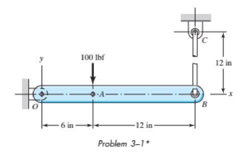
The free body diagram of each element of the given figure.
The magnitude and direction of each force.
Answer to Problem 1P
The free body diagram of element OB is shown in Figure (1).
The free body diagram of element BC is shown in Figure (2).
The free body diagram of pin joint C is shown in Figure (3).
The free body diagram of pin joint O is shown in Figure (4).
The magnitude of force at O is
The magnitude of force at B is
The magnitude of force at C is
Explanation of Solution
Figure (1) shows the free body diagram of the element OB.
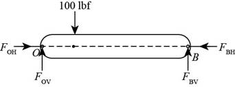
Figure (1)
Write the net moment at point O on the link OB.
Here, perpendicular distance between point O and
Write the net reaction force in the vertical direction on the link OB.
Here, force acting at point O is
Write the net reaction force in the horizontal direction on the link OB.
Here, force acting at point O is
Figure (2) shows the free body diagram of element BC.
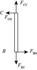
Figure (2)
Write the net reaction force in the horizontal direction on the link BC.
Here, force acting at point B is
Write the net reaction force in the vertical direction on the link OB.
Here, force acting at point C is
Figure (3) shows the free body diagram of pin joint C.
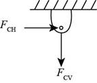
Figure (3)
Write the expression of net reaction force at pin joint C in horizontal direction.
Here, force acting at point C in the horizontal direction is
The force acting in the vertical direction at point C is balanced by the reaction force by link BC at point C.
Figure (4) shows the free body diagram of the pivot point O.
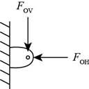
Figure (4)
Write the expression of net reaction force at pin joint O in horizontal direction.
Here, force acting at point O in the horizontal direction is
The force acting in the vertical direction at point O is balanced by the reaction force by link OB at point O.
Conclusion
Substitute
Thus, the vertical component of the force at point
Substitute
Thus, the vertical component of the force at point
Substitute
Thus, the vertical component of the force at point
Substitute
Thus, the horizontal component of the force at point
Substitute
Thus, the horizontal component of the force at point
Thus, the magnitude of force at O is
Thus, the magnitude of force at B is
Thus, the magnitude of force at C is
Want to see more full solutions like this?
Chapter 3 Solutions
Shigley's Mechanical Engineering Design (McGraw-Hill Series in Mechanical Engineering)
Additional Engineering Textbook Solutions
Fox and McDonald's Introduction to Fluid Mechanics
Heating Ventilating and Air Conditioning: Analysis and Design
Thermodynamics: An Engineering Approach
Mechanics of Materials (10th Edition)
Mechanics of Materials
Thinking Like an Engineer: An Active Learning Approach (3rd Edition)


- Solve the preceding problem for the following data: b = 8.0 in., k = 16 lb/in., a = 45°, and P = 10 lb.arrow_forwardFrame ABC has a moment release just left of joint B. Find axial force N, shear force V, and moment M at the top of column AB. Write variables N, V, and M in terms of variables P and L.arrow_forwardConsider a rigid rod that is subjected to two external forces and is fixed to the wall at A. The following figure displays the rod's free body diagram. Answer the following questions using the provided FBD. 2.5 -1 1 3.5 The support reaction at A along x-axis (A) is The support reaction at A along y-axis (Ay) is The support reaction at A along z-axis (A.) is The Moment reaction at support A about x-axis (Ma) is -1 n 1 0 -2.5 2.5 -1 -3.5 5.5 -5.5 -0.5 0.5 A₂ Mx4 Z M₂ My KN KN KN 3m KN.m 1m 1 KN 2m 2.5 KNarrow_forward
- The figure shows a rigid bar that is supported by a pin at A and two rods, one made of steel and the other of bronze. Neglecting the weight of the bar, compute the force (in N) in the steel rod caused by the 42758-Nload, using the following data: length of steel = 1.27 m, length of bronze = 2.06 m Area of steel = 522 mm, Area of bronze = 239 mm Modulus of elasticity of steel = 216 Gpa, Modulus of elasticity of bronze = 84 Gpa x= 0.69 m, y = 1.08 m, and z = 0.86 m. Round off the final answer to three decimal places. ... Bronze Steel Ey te zarrow_forwardThe figure shows a rigid bar that is supported by a pin at A and two rods, one made of steel and the other of bronze. Neglecting the weight of the bar, compute the force (in N) in the bronze rod caused by the 45846-Nload, using the following data: length of steel = 11 m, length of bronze = 2.3 m Area of steel = 562 mm, Area of bronze = 335 mm Modulus of elasticity of steel = 195 Gpa, Modulus of elasticity of bronze = 80 Gpa x= 0.55 m, y = 1.12 m, and z = 0.78 m. Round off the final answer to two decimal places. ... Bronze Steelarrow_forwardENTER YOUR ANSWER THE WAY I SPECIFY HERE IN ADDITION TO DOING IT ON SCRATCH PAPER 400 N 800 N B D A E C 2 m Use the method of sections to calculate the axial force in members AC and BC. Enter your answer in the following way rounded to the nearest whole number. Example If your answer is TAC 2 N tension TBC =3.1 N compression. enter 2Tension;3Compression Enter TAC then TBC (no space)arrow_forward
- 1) Given the figure below, answer the following questions: a) What are the x and y components offorce F? (use Fx and Fy)b) What are the x and y components offorce P? (use Px and Py)(Hint: The x-y plane is differentfrom the true horizontal and verticalaxes)c) What are the vertical and horizontalcomponents of force F? (use Fh & Fv)d) What are the vertical and horizontalcomponents of force P? (use Ph & Pv)e) What is the magnitude of the resultant?f) What angle does the resultant make withthe horizontal axisg) What angle does the resultant makewith the inclined x-axis.arrow_forward1: The forces as given below are applied as shown in the figure. Fi=10 kN, F2=5 kN and F3=3 kN. The diameter of the circular bar is 40 mm. Calculate the followings at point D; a) o and tp b) Principal stresses c) o, based on maximum principal stress theory d) o, based on maximum shear stress theory e) o, based on maximum deformation energy theory (Von Mises) F2 F3 F1 D 150 mm 350 mmarrow_forwardIn the following armor find the forces in the members CD, KD and JK of section 1-1 indicated in the figure.arrow_forward
 Mechanics of Materials (MindTap Course List)Mechanical EngineeringISBN:9781337093347Author:Barry J. Goodno, James M. GerePublisher:Cengage Learning