
Concept explainers
Videos
The Norton and Thevenin equivalent networks from node
Answer to Problem 3.71HP
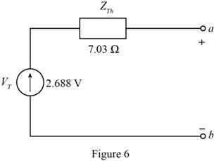
The Thevenin equivalent Network is shown in Figure 6 and the Norton equivalent network is shown in Figure 4
Explanation of Solution
Calculation:
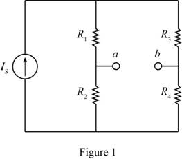
The given diagram is shown in Figure 1
To determine the Norton equivalent, short circuit the output terminals, Mark the values, current direction, and redraw the circuit.
The required diagram is shown in Figure 2
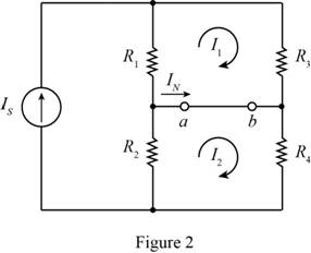
Apply KVL to the first loop.
Apply KVL to the second loop.
The equation for the Norton current is given by,
Substitute
To obtain the Norton resistance of the circuit, short circuit the voltage source, open circuit the current source and redraw the circuit.
The required diagram is shown in Figure 3
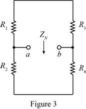
Form the above circuit the Norton impedance of the circuit is calculated as,
Substitute
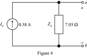
Mark the values and draw the Norton equivalent circuit.
The required diagram is shown in Figure 4
To calculate the Thevenin voltage, remove the load resistance and redraw the circuit.
The required diagram is shown in Figure 5
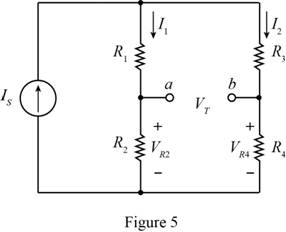
From the above circuit the value of the current
Substitute
The expression for the value of the current
Substitute
The expression for the voltage across the resistor
Substitute
The expression for the voltage across the resistor
Substitute
From Figure (5), the expression for the Thevenin voltage is given by,
Substitute
The Thevenin and the Norton resistance of the circuit are equal, thus the expression for the Thevenin resistance is given by,
Substitute
Mark the values and draw the Thevenin equivalent of the circuit.
The required diagram is shown in Figure 6
Conclusion:
Therefore, the Thevenin equivalent Network is shown in Figure 6 and the Norton equivalent network is shown in Figure 4
Want to see more full solutions like this?
Chapter 3 Solutions
Principles and Applications of Electrical Engineering


- Consider the series-parallel circuit shown in the figure below with various multimeters connected in the circuit. Assum that XMM1 has been configured in ammeter mode, and XMM2 has been configured in voltmeter mode. XMM1 R1 1kQ XMM2 R2 R3 V1 1kQ 1kQ 12V 3.1: Redraw the circuit replacing XMM1 and XMM2 by their equivalent circuit models 3.2: Assume that XMM2 was incorrectly configured in ammeter mode. Redraw the equivalent circuit from 3.1 and compute the current that would be measured by the ammeter in this scenario. Hil-arrow_forwardUse the Principle of Superposition to determine the current i through R3 in the Figure. Let R1 = 100, R2 = 40, R3 = 20, R4 = 20, R5= 20, Vs 10 V, Is = 2A. ww VS R3 ww wwwarrow_forwardQ3) For the network shown in the figure below, determine the following: a) fe b) Zinl and Zin2 c) Zo1 and Zo2 d) Avı, Av2, and AVT +20 V 6.8 kQ 30 ka 6.8 ka 30 ka 0.5 F 0.5 uF P-150 B- 150 1.5 ka 50 uF 1.5 ka 50 uFarrow_forward
- Refer to the given circuit below. Using Superposition Theorem, determine the percent contribution of E₁ to the current through R3 (lbc)- R3E1 % contribution = x 100 R3E1+1R3E2+¹R31 R1 R2 R3 R4 E₁ E2 T 8 Ω 6Q 4Q 7 V 11 V 5 A R₂ C ΤΩ R₁ E₁ a b R3 RA E₂arrow_forwardAccording to the circuit and parameters given in the figure, make your calculations and write the table. wmww w n ww bbn m w w w w Please fill in. www ww w +12V +12V M1 M2 2kN 10kN K ImA/V² 0.5mA/V² VTH 2V 1.5V 22kN M2 MODE 33k2 M1 Ip 1kN VGS Vps K1=lmA/V² Vth1=2V; M2: K2=0.5mA/V² VTH2=1.5Varrow_forwardO Given the information appearing in the Figure, Fird the level of resistance for Ri e R3. RI 3 o 14V Rgarrow_forward
- 3.40 Find Vi and V in the circuit shown in Figure P340. FIGURE P3.40 2 kn R2 V2 4 kn 2000 i 5 V 3 kn 2.5 k 45arrow_forward8-13 E (a) Formulate mesh-current equations for the cir- cuit in Figure P3-13. (b) Formulate node-voltage equations for the circuit in Figure P3-13. (c) Which set of equations would be easier to solve? Why? (d) Using MATLAB, find , and i, in terms of the mesh- current variables. SSarrow_forwardQ3: Suppose that the components of the circuit shown in figure below have the following values: RI= SkD, R2= 9kΩ, R3-10kΩ , R4-5kΩ, R5-10kΩ, R6-9k Ω. The voltage across AB is measured by a voltmeter whose internal resistance is 95k2. What is the measurement error caused by the resistance of the measuring instrument? R3 Rs RM Ri SMA Fo Em Ry Barrow_forward
- Calculate the lx current using the constant voltage model for the circuit in the figure. Circuit Parameters / Vx=12 V, VD ON=800 mV, R1=1.3 k2 Vx D1 VD a. 13.354 mA O b. 10.769 mA O c. 8.615 mA O d. 15.938 mA e. 6.462 mAarrow_forward6. A Thevenin de equivalent circuit always consists of an equivalent.. a. AC voltage source b. capacitance c. DC voltage source d, resistance 7. The superposition theorem is useful for the analysis of. ***** a. single-source circuits. b. only two-source circuits. c. multi-source circuits. d. no source circuits.arrow_forward4) Use the Thevenin equivalent circuit technique to find Vab (a) without the load circuit connected (source circuit only) and (b) with the load circuit connected. (c) Using only one additional circuit element, to be connected across the ab terminals, sketch a circuit that would prevent the loading effect of the load circuit on the source circuit voltage. Please sketch this final circuit using the Thevenin equivalents from parts a and b. 3i1 SOURCE LOAD 2kN 3kN 2kN a 24V 4mA 8kQ 2k2 1kQ b 2000lxarrow_forward
 Introductory Circuit Analysis (13th Edition)Electrical EngineeringISBN:9780133923605Author:Robert L. BoylestadPublisher:PEARSON
 Delmar's Standard Textbook Of ElectricityElectrical EngineeringISBN:9781337900348Author:Stephen L. HermanPublisher:Cengage Learning
 Programmable Logic ControllersElectrical EngineeringISBN:9780073373843Author:Frank D. PetruzellaPublisher:McGraw-Hill Education
 Fundamentals of Electric CircuitsElectrical EngineeringISBN:9780078028229Author:Charles K Alexander, Matthew SadikuPublisher:McGraw-Hill Education
 Electric Circuits. (11th Edition)Electrical EngineeringISBN:9780134746968Author:James W. Nilsson, Susan RiedelPublisher:PEARSON
 Engineering ElectromagneticsElectrical EngineeringISBN:9780078028151Author:Hayt, William H. (william Hart), Jr, BUCK, John A.Publisher:Mcgraw-hill Education,