
Concept explainers
Videos
The reaction force equation at point
The reaction force equation at point
The shear force equation for section
The shear force equation for section
The bending moment equation for section
The bending moment equation for section
The deflection equations for section
The deflection equations for section
Answer to Problem 18P
The reaction force equation at point
The reaction force equation at point
The shear force equation for section
The shear force equation for section
The bending moment equation for section
The bending moment equation for section
The deflection equations for section
The deflection equations for section
Explanation of Solution
Write the balanced force equation in vertical direction.
Here, the reaction at point
Take the net moment about point
Thus, the reaction force at point A is
Substitute
Thus, the reaction force at point
Take a section at a distance
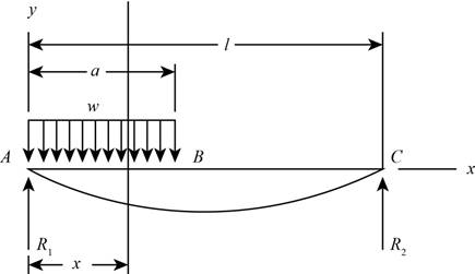
Figure (1)
Write the shear force equation for part AB.
Here, the shear force for the section
Substitute
Thus, the shear force equation for region
Take a section at a distance
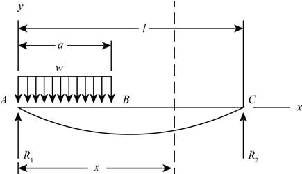
Figure (2)
Write the shear force equation for part
Here, the shear force for the section
Substitute
Thus, the shear force equation for region
Write the moment equation for section
Here, the moment for the section
Substitute
Thus, the bending moment equation for region AB is
Write the moment equation for section
Here, the moment for the section
Substitute
Thus, the bending moment equation for region
Write the bending moment equation for section
Here, Young’s modulus of the beam is
Substitute
Integrate Equation (VI).
Here, the integration constant is
Integrate Equation (VII).
Here, the second integration constant is
Substitute
Substitute
Here, the deflection for the section
Substitute
Thus, the beam deflection equation for region AB is
Write the bending moment equation for section
Here, the moment for the section
Substitute
Integrate the Equation (X).
Here, the first integration constant is
Integrate the Equation (XI).
Here, the second integration constant is
Substitute
Substitute
At
Equate the right hand side of equation (XI) and (XIII) and substitute
At
Substitute
Substitute
Substitute
Substitute
Solve the equation further,
Substitute
Thus, the beam deflection equation for region BC is
Want to see more full solutions like this?
Chapter 4 Solutions
Shigley's Mechanical Engineering Design (McGraw-Hill Series in Mechanical Engineering)


- Repeat Problem 2.5-9 for the flat bar shown in the figure but assume that and thatarrow_forwardSolve the preceding problem for the following data: b = 8.0 in., k = 16 lb/in., a = 45°, and P = 10 lb.arrow_forwardCompare the angle of twist 1 for a thin-walled circular tube (see figure) calculated from the approximate theory for thin-walled bars with the angle of twist 2 calculated from the exact theory of torsion for circular bars, Express the ratio 12terms of the non-dimensional ratio ß = r/t. Calculate the ratio of angles of twist for ß = 5, 10, and 20. What conclusion about the accuracy of the approximate theory do you draw from these results?arrow_forward
- Solve the following problem and SHOW YOUR COMPLETE SOLUTIONS. ILLUSTRATE THE FREE BODY DIAGRAM for better understanding.arrow_forwardSOLVE STEP BY STEP IN DIGITAL FORMAT THANKS For the beam in shown in the figure, determine the vertical displacement in C 6, and the turn in BDB by Castigliano's Theorem in terms of El. L 2 C L 2 Barrow_forward4- For the shaper mechanism shown in the figure, OA = 50 mm, QB = 350 mm, BC = 170 mm, OQ = 140 mm. Find the displacement slider 6. %3D 120arrow_forward
- Find the torsion angle of the free end with respect to the fixed end of the system in the figure. the material is steel and the dimensions are in cm. please make no mistake, they helped me in one and it was wrongarrow_forward2. The figure shows a spring chair. The chair weight is 100 N. The spring free-length is 500 mm, mean diameter is 200 mm, wire diameter is 10 mm and number of turns is 12. The spring wire material is Music wire A228 with modulus of rigidity of 82700 MPa. Calculate the initial deflection of the spring under the chair weight. If a child seats on the chair, calculate his weight to bush the spring to the shut height. Calculate the stresses in the spring at that condition. BFD'N y = d*G 8FD T = K, 4C +2 K = 4C – 3 D C = --- o00000000odarrow_forward4 kN 3 kN 375 mm B 375 mm 750 mm As shown in the figure, the shaft is supported by bearings A and B and is subjected to a concentrated load. Material A-36 steel Diameter: 50 mm Find the maximum displacement and maximum stress. 1) Determine the theoretical stress value using the stress formula due to bending load. 2) Model with a solid model to obtain stress values and displacements at Creosimulate. 3) Model with Beam model to obtain stress values and displacements at Creosimulate.arrow_forward
- The dimensions are of the graph are d1 = 7 cm , L1 = 6 m , d2 = 4.2 cm , and L2 = 5 m with applied loads F1 = 130 kN and F2 = 60 kN . The modulus of elasticity is E = 80 GPa . Use the following steps to find the deflection at point D. Point B is halfway between points A and C. What is the reaction force at A? Let a positive reaction force be to the right.arrow_forwardConsider a wooden rectangular slab of mass M, length L, and width W nailed vertically to a wall. The nail is located approximately at the middle of the top edge (see Figure 1). You use a hammer to hit the bottom right corner with an average force F, and the hammer is contact with the slab for a small time Δt. The moment of inertia for the axis passing through the center of the slab, pointing away from the wall, is I=(1/12)M(L^2+W^2). a) What is the angular speed of the slab about the nail just after you have hit the slab? Explain every part of your working carefully; in particular, state any assumptions you make. Hint: consider ττ=dL/dt. Use the torque due to the force exerted by the hammer. b) What is the angular speed of the slab when the slab becomes vertical (see Figure 2)? You should be able to do this even if you didn't manage to do the previous part. What is the minimum value of F for a given Δt such that the slab does become vertical? c) What would have happened if the nail was…arrow_forwardSOLVE STEP BY STEP IN DIGITAL FORMAT THANKS For the beam in shown in the figure, determine the vertical displacement in C 6, and the turn in BD by Castigliano's Theorem in terms of El. L 2 C L 2 B varianarrow_forward
 Mechanics of Materials (MindTap Course List)Mechanical EngineeringISBN:9781337093347Author:Barry J. Goodno, James M. GerePublisher:Cengage Learning