
Videos
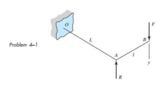
The figure shows a torsion bar OA fixed at O, simply supported at A, and connected to a cantilever AB. The spring rate of the torsion bar is kT, in newton-meters per radian, and that of the cantilever is kl, in newtons per meter. What is the overall spring rate based on the deflection y at point B?
The overall spring rate based on the deflection
Answer to Problem 1P
The overall spring rate based on the deflection
Explanation of Solution
Write the expression for the stiffness of the torsion bar.
Here, the torsional stiffness of the bar is
Write the expression of the torque on the torsional bar.
Here, the length of the bat is
Since the force
Substitute
Write the expression for stiffness of the cantilever portion AB.
Here, the lateral stiffness of the bar is
Write the expression for net deflection of a combined system.
Here, total deflection is
The net defection of the combined system is the combination of the torsional deflection and lateral deflection.
Write the equation of net deflection of the combined system.
Conclusion:
Substitute the value of
Substitute
Thus, the overall spring rate based on the deflection
Want to see more full solutions like this?
Chapter 4 Solutions
Shigley's Mechanical Engineering Design (McGraw-Hill Series in Mechanical Engineering)


- 3. Find the torsional deflection of a solid steel shaft 100 mm in diameter and 130 mm long subjected to twisting moment of 3 x 10⁶ N-mm. The torsional modulus of elasticity is 80,000 N/mm2.arrow_forwardB/ A steel robotic arm carries a payload of (444.82 kg) has a dimension of (1.524 m) length, (0.1524 m) height and of (0.102 m) breadth. The steel Young's modulus, (E= 206.85GPA) and density of (p=7.87 kgm'). Find the robotic arm deflection.arrow_forwardIn shaft assembly shown in Figure 1, 1= 200 mm, a = 160 mm, b = 180 mm, the force P = 1000 N/cm. Determine the maximum deflections in torsion and in bending of the shaft shown in Figure 1, if the steel shaft diameter is 40 mm. Young's modulus E= 206.8 GPa, Mod of rigidity G = 80.8 GPa d bearings are self-aligning so act as simple supports 区区arrow_forward
- SOLVE STEP BY STEP IN DIGITAL FORMAT THANKS For the beam in shown in the figure, determine the vertical displacement in C & and the rotation in A₁ using Castigliano's Theorem. E = 200 GPa; 1= 150X10° mm¹. 8 kN/m -4 m 20 KN C 4 m Barrow_forward3) For a torsional window-shade spring shown as figure, determine the maximum operating moment and corresponding angular deflection. Given: Thickness, h : Music Wire :1.625 mm • Mean coil diameter : 25 mm • Number of active coil : 350 Spring Material Wire diameter • Factor of safety :1.5arrow_forwardQ2 Find the deflection at the tip of the cantilever shown in figure below. Use EI=20MNm². 1m 30kN/m 10kN 1m 25kNarrow_forward
- A solid steel post is subjected to pure torsion. Given: -post Diameter = 65 mm -length = 2.75 m -torque = 2.4 kN-m -shear Modulus of Elasticity = 78 GPa Question: What is the Polar Moment of Inertia of the Post?arrow_forwardMechanics of Deformable Bodies The rigid beam of negligible weight is supported by a pin at o and two vertical rods. Find the vertical displacement of the 50-kip weight. Bronze A = 2 in.? E = 12 x 106 psi Steel 10 ftA = 0.5 in.2 E= 29 x 10° psi 3 ft 3 ft- 8 ft- 50 kipsarrow_forward2. The figure shows a spring chair. The chair weight is 100 N. The spring free-length is 500 mm, mean diameter is 200 mm, wire diameter is 10 mm and number of turns is 12. The spring wire material is Music wire A228 with modulus of rigidity of 82700 MPa. Calculate the initial deflection of the spring under the chair weight. If a child seats on the chair, calculate his weight to bush the spring to the shut height. Calculate the stresses in the spring at that condition. BFD'N y = d*G 8FD T = K, 4C +2 K = 4C – 3 D C = --- o00000000odarrow_forward
- The figure illustrates a stepped torsion-bar spring OA with an actuating cantilever AB. Both parts are of carbon steel (Young's modulus is 207 GPa and shear modulus is 79.3 GPa). Use Castigliano's theorem to find the spring rate k corresponding to a force F acting at B. Hint: you need to consider the bending of member AB and torsion of member AO. 18 mm, 12 mm 0.2 m 0.4 m 8 mm 0.2 m Barrow_forwardes A gear reduction unit uses the countershaft shown in the figure. Gear A receives power from another gear with the transmitted force FA applied at the 20° pressure angle as shown. The power is transmitted through the shaft and delivered through gear B through a transmitted force Fg at the pressure angle shown. For the steel countershaft specified in the table, find the deflection and slope of the shaft at point A. Use superposition with the deflection equations in Table A-9. Assume the bearings constitute simple supports. In the figure below, FA is 310 lbf and the diameter of the shaft (dshaft) is 1.29 in. dshaft Gear A 20-in dia. 16 in FA 20⁰ The deflection at point A is The slope at point A is 14 in 100 Gear B 8-in dia. rad. 9 in in. B FB 20°arrow_forwardProb # 3. Find the torsional deflection of a solid steel shaft 100 mm in diameter and 130 mm long subjected to twisting moment of 3 x 10⁶ N-mm. The torsional modulus of elasticity is 80,000 N/mm2. a. 122 deg b. 285 deg c. 0.234 deg d. 0.543 degarrow_forward
 Elements Of ElectromagneticsMechanical EngineeringISBN:9780190698614Author:Sadiku, Matthew N. O.Publisher:Oxford University Press
 Mechanics of Materials (10th Edition)Mechanical EngineeringISBN:9780134319650Author:Russell C. HibbelerPublisher:PEARSON
 Thermodynamics: An Engineering ApproachMechanical EngineeringISBN:9781259822674Author:Yunus A. Cengel Dr., Michael A. BolesPublisher:McGraw-Hill Education
 Control Systems EngineeringMechanical EngineeringISBN:9781118170519Author:Norman S. NisePublisher:WILEY
 Mechanics of Materials (MindTap Course List)Mechanical EngineeringISBN:9781337093347Author:Barry J. Goodno, James M. GerePublisher:Cengage Learning
 Engineering Mechanics: StaticsMechanical EngineeringISBN:9781118807330Author:James L. Meriam, L. G. Kraige, J. N. BoltonPublisher:WILEY