
Applied Statics and Strength of Materials (6th Edition)
6th Edition
ISBN: 9780133840544
Author: George F. Limbrunner, Craig D'Allaird, Leonard Spiegel
Publisher: PEARSON
expand_more
expand_more
format_list_bulleted
Concept explainers
Videos
Textbook Question
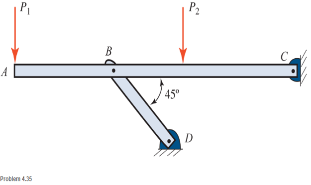
Chapter 4, Problem 4.35SP
For the structure shown, draw free-body diagram for both the beam ABC and the link BD. The members are weightless.
Expert Solution & Answer

Learn your wayIncludes step-by-step video

schedule06:07
Students have asked these similar questions
Calculate the support reactions, calculate internal forces on the designated section C.
1) Use the method of Joints to calculate the force in each member of the loaded truss illustrated and state weather each member is in tension or compression. Also calculate the reaction forces at a and e.
Draw the free-body diagram of member AB, which is supported by a roller at A and a pin at B. Compute the support reactions at A and B.
Chapter 4 Solutions
Applied Statics and Strength of Materials (6th Edition)
Ch. 4 - and 4.2 Sketch free-body diagram for the members...Ch. 4 - Sketch free-body diagram for the members shown.Ch. 4 - A steel cylinder having a mass of 120 kgis...Ch. 4 - A 50-lb block is supported by a pin support and a...Ch. 4 - A cylinder weighing 200 lb is supported on an...Ch. 4 - A weight W is supported by a flexible cable and an...Ch. 4 - The ladder shown is supported by a smooth...Ch. 4 - What horizontal force F applied at the center of...Ch. 4 - Calculate the force in cable AB and the angle (...Ch. 4 - Calculate the horizontal force F that should be...
Ch. 4 - Calculate the reactions of the two smooth inclined...Ch. 4 - Calculate the force in each cable for the...Ch. 4 - Three members of a truss intersect at joint B as...Ch. 4 - Four concurrent forces in equilibrium act at point...Ch. 4 - The beam shown carries vertical concentrated...Ch. 4 - Find the reactions at A and B for the beam shown....Ch. 4 - A simply supported beam spans 10 m. The beam...Ch. 4 - The beam shown carries vertical loads. Calculate...Ch. 4 - Calculate the reaction at each support for the...Ch. 4 - Calculate the reactions at A and B for the beam...Ch. 4 - Calculate the reactions at A and B for the beam...Ch. 4 - A 12-ft simple beam is supported at each end. It...Ch. 4 - The beam shown carries vertical loads as...Ch. 4 - Determine the reactions for the beam shown. The...Ch. 4 - Calculate the reaction at each support for the...Ch. 4 - Calculate the wall reactions for the cantilever...Ch. 4 - Determine the reactions at supports A and B of the...Ch. 4 - A mass M of 300 kg is supported by a boom, as...Ch. 4 - Rework Problem 4.28 assuming that point D has been...Ch. 4 - Calculate the force in the tie rod BC and the...Ch. 4 - The davit shown is used in pairs for...Ch. 4 - For the following computer problems, any...Ch. 4 - For the following computer problems, any...Ch. 4 - For the following computer problems, any...Ch. 4 - For the structure shown, draw free-body diagram...Ch. 4 - A 1200-lb load is supported by a cable that runs...Ch. 4 - For the pin-connected frame shown, sketch a...Ch. 4 - For the concurrent force system shown, calculate...Ch. 4 - A strut having a mass of 40 kg/m is supported by a...Ch. 4 - Calculate the reaction at each support for the...Ch. 4 - Calculate the reaction at each support for the...Ch. 4 - A beam supports a nonuniformly distributed load as...Ch. 4 - Calculate the reactions at each support for the...Ch. 4 - Compute reactions at each support for the beam...Ch. 4 - A rod of uniform cross section weighs 4 lb/ft and...Ch. 4 - A 12-ft-long weightiness member supports two...Ch. 4 - A uniform rod AB, having a weight of 5.00 lb and a...Ch. 4 - The plastic barrel tent anchor of Problem 2.11...Ch. 4 - Compute the reactions at A and B for the bracket...Ch. 4 - The truss shown is supported by a pin at A and a...Ch. 4 - Find the reactions at supports A and B for the...Ch. 4 - Find the reactions at supports A and B for the...Ch. 4 - Determine the reactions at A and B for the truss...Ch. 4 - A 40-ft ladder weighing 130 lb is pin-connected to...Ch. 4 - The frame shown is pin-connected at point A and...Ch. 4 - Prob. 4.56SPCh. 4 - A horizontal beam is pin-connected to a wall at...Ch. 4 - Calculate the force in the cable for the structure...Ch. 4 - The Thenard shutter dam shown was originally...Ch. 4 - An inclined railway can be used to lift heavy...Ch. 4 - Two cylinders are supported in a box, as shown....
Additional Engineering Textbook Solutions
Find more solutions based on key concepts
The 60 mm-diameter steel shaft is subjected to the torques shown. Determine the angle of twist of end A with re...
Mechanics of Materials (10th Edition)
Determine the components of the force acting parallel and perpendicular to the axis of the pole. Prob. F2-30
Engineering Mechanics: Statics
1.1 What is the difference between an atom and a molecule? A molecule and a crystal?
Manufacturing Engineering & Technology
The quantity ms into s.
Engineering Mechanics: Statics & Dynamics (14th Edition)
What parts are included in the vehicle chassis?
Automotive Technology: Principles, Diagnosis, and Service (5th Edition)
What parts are included in the vehicle chassis?
Automotive Technology: Principles, Diagnosis, And Service (6th Edition) (halderman Automotive Series)
Knowledge Booster


Learn more about
Need a deep-dive on the concept behind this application? Look no further. Learn more about this topic, mechanical-engineering and related others by exploring similar questions and additional content below.Similar questions
- Identify the zero force members in the following truss.arrow_forwardFind the support reactions. Determine the force in each member of the truss. Draw a summary diagram clearly showing your results. Be sure to identify any zero force members in the summary diagram.arrow_forwardPlease help me identify the zero force members in this truss.arrow_forward
- A simply supported truss is shown below. There is a pin support at A anda roller support at D. Determine the support reactions and the internalforce in each member. Use the method of jointsarrow_forwardMethod of Sections: Calculate the reaction at A and all force members. Assume F1 = 9500 lb and F2 = 4500 lbarrow_forwardCompute the reaction forces at support A and B in terms of w0, with the aid of free body diagram.arrow_forward
- Homework (2) Q1/ The 500-kg uniform beam is subjected to the three external loads shown. Compute the reactions at the support point O. The x-y plane is vertical. y I. 30 15 kN-m 3 kN A B 1.4 kN 1.2 m 1.8 m 1.8 marrow_forwardClaculate the wall reactions for the cantilever truss shown. the upper support is pinned and the lower support is a roller. Neglect the weight of the truss.arrow_forwardCalculate the force in member GH of the truss and indicate whether it is in tension or compression, using either method of joints or method of sections. Required: Draw the FBD(s) as needed for analysis-all equilibrium equations must correspond to a FBD that you have drawn. Make sure to clearly indicate which FBD your equation(s) correspond to. K J H 4 ft C - 3 ft 3 ft -- 3 ft- 3 ft-3 ft 1500 lb 1500 lb 1500 lb 1500 lb 1500 lbarrow_forward
- The T-bar AEBF is connected to rod CD, with the joint at F being equivalent to a slider bearing. The supports at A and C are slider bearings, and thrust bearings are found at B and D. The two applied forces, which act at the midpoint of the arm EF, are parallel to the y- and z-axes, respectively. Neglecting the weights of the members, draw the FBDs for the entire structure, the T-bar, and rod CD. Determine the total number of unknowns.arrow_forwardDetermine all the member forces in the truss shown in the figure. Identify which members are in compression and which are in tension. The self-weight of the structure is not considered.arrow_forwardProblem 2: For the frame shown, find the horizontal and vertical components of the reactions at A and C. The cable supports a mass of 100kg. Assume the pulley is frictionless. 0.3 m Partial Ans. Cx = 654 N 1.5 m 2 m 0.5 marrow_forward
arrow_back_ios
SEE MORE QUESTIONS
arrow_forward_ios
Recommended textbooks for you
 Elements Of ElectromagneticsMechanical EngineeringISBN:9780190698614Author:Sadiku, Matthew N. O.Publisher:Oxford University Press
 Mechanics of Materials (10th Edition)Mechanical EngineeringISBN:9780134319650Author:Russell C. HibbelerPublisher:PEARSON
 Thermodynamics: An Engineering ApproachMechanical EngineeringISBN:9781259822674Author:Yunus A. Cengel Dr., Michael A. BolesPublisher:McGraw-Hill Education
 Control Systems EngineeringMechanical EngineeringISBN:9781118170519Author:Norman S. NisePublisher:WILEY
 Mechanics of Materials (MindTap Course List)Mechanical EngineeringISBN:9781337093347Author:Barry J. Goodno, James M. GerePublisher:Cengage Learning
 Engineering Mechanics: StaticsMechanical EngineeringISBN:9781118807330Author:James L. Meriam, L. G. Kraige, J. N. BoltonPublisher:WILEY
Elements Of Electromagnetics
Mechanical Engineering
ISBN:9780190698614
Author:Sadiku, Matthew N. O.
Publisher:Oxford University Press
Mechanics of Materials (10th Edition)
Mechanical Engineering
ISBN:9780134319650
Author:Russell C. Hibbeler
Publisher:PEARSON
Thermodynamics: An Engineering Approach
Mechanical Engineering
ISBN:9781259822674
Author:Yunus A. Cengel Dr., Michael A. Boles
Publisher:McGraw-Hill Education
Control Systems Engineering
Mechanical Engineering
ISBN:9781118170519
Author:Norman S. Nise
Publisher:WILEY
Mechanics of Materials (MindTap Course List)
Mechanical Engineering
ISBN:9781337093347
Author:Barry J. Goodno, James M. Gere
Publisher:Cengage Learning
Engineering Mechanics: Statics
Mechanical Engineering
ISBN:9781118807330
Author:James L. Meriam, L. G. Kraige, J. N. Bolton
Publisher:WILEY
Types Of loads - Engineering Mechanics | Abhishek Explained; Author: Prime Course;https://www.youtube.com/watch?v=4JVoL9wb5yM;License: Standard YouTube License, CC-BY