
Mechanics of Materials
9th Edition
ISBN: 9780133254426
Author: Russell C. Hibbeler
Publisher: Prentice Hall
expand_more
expand_more
format_list_bulleted
Concept explainers
Videos
Textbook Question
Chapter 4.2, Problem 4.5PP
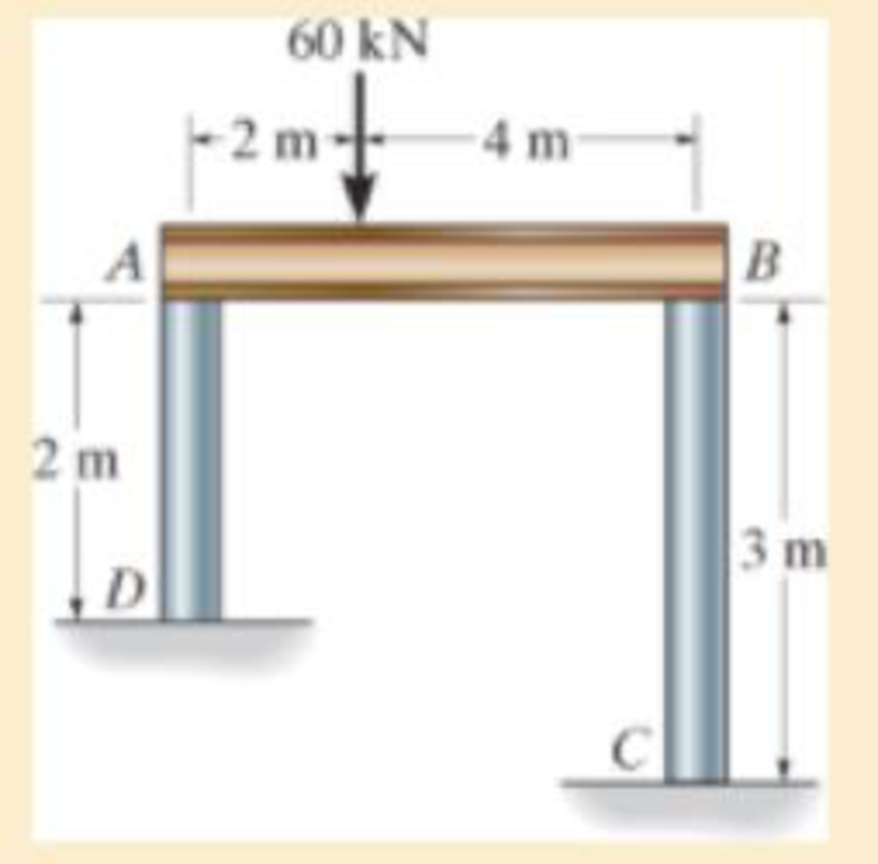
The rigid beam supports the load of 60 kN. Determine the displacement at B. Take E = 60 GPa, and ABC = 2 (10-3) m2.
P4–5
Expert Solution & Answer

Learn your wayIncludes step-by-step video

schedule05:08
Students have asked these similar questions
2-1. The steel framework is used to support the
reinforced stone concrete slab that is used for an office.
The slab is 200 mm thick. Sketch the loading that acts
along members BE and FED. Take a = 2 m, b = 5 m.
Hint: See Tables 1.2 and 1.4.
B
8
E
D
Find the support reactions at the fixed support
O. The beam has a mass of 500 kg, and it has a uniform cross section.
1.2 m
A
1.4 kN
1.8 m
15 kN.m
B
●
1.8 m
30°
3 kN
x
A moment about the z-axis of 192 N-m is applied to a beam with dimensions b = 85 mm and h = 302 mm. If there are no other loads applied to the beam (My, P, Vy and Vz = 0), what is the normal stress at point F? Give your answer in
kPa to two decimal places with negative indicating compression and positive indicating tension.
b/4
М,
h
E
Ihis
F
h/3
В
M.
D
b/4
Chapter 4 Solutions
Mechanics of Materials
Ch. 4.2 - In each case, determine the internal normal force...Ch. 4.2 - Determine the internal normal force between...Ch. 4.2 - The post weighs 8kN/m. Determine the internal...Ch. 4.2 - The rod is subjected to an external axial force of...Ch. 4.2 - The rigid beam supports the load of 60 kN....Ch. 4.2 - The 20-mm-diameter A-36 steel rod is subjected to...Ch. 4.2 - Segments AB and CD of the assembly are solid...Ch. 4.2 - The 30-mm-diameter A992 steel rod is subjected to...Ch. 4.2 - If the 20-mm-diameter rod is made of A-36 steel...Ch. 4.2 - The 20-mm-diameter 2014-T6 aluminum rod is...
Ch. 4.2 - The 20-mm-diameter 2014-T6 aluminum rod is...Ch. 4.2 - Prob. 4.1PCh. 4.2 - The copper shaft is subjected to the axial loads...Ch. 4.2 - The composite shaft, consisting of aluminum,...Ch. 4.2 - The composite shaft, consisting of aluminum,...Ch. 4.2 - 4-5. The assembly consists of a steel rod CB and...Ch. 4.2 - 4-6. The bar has a cross-sectional area of 3 in2,...Ch. 4.2 - 4–7. If P1 = 50 kip and P2 = 150 kip, determine...Ch. 4.2 - *4-8. If the vertical displacements of end A of...Ch. 4.2 - The assembly consists of two 10-mm diameter red...Ch. 4.2 - The assembly consists of two 10-mm diameter red...Ch. 4.2 - The load is supported by the four 304 stainless...Ch. 4.2 - The load is supported by the four 304 stainless...Ch. 4.2 - The rigid bar is supported by the pin-connected...Ch. 4.2 - Prob. 4.14PCh. 4.2 - Prob. 4.15PCh. 4.2 - *4-16. The hanger consists of three 2014-T6...Ch. 4.2 - 4-17. The hanger consists of three 2014-T6...Ch. 4.2 - Prob. 4.18PCh. 4.2 - Prob. 4.19PCh. 4.2 - The assembly consists of three titanium...Ch. 4.2 - Prob. 4.21PCh. 4.2 - Prob. 4.22PCh. 4.2 - Prob. 4.23PCh. 4.2 - Determine the relative displacement of one end of...Ch. 4.2 - Prob. 4.25PCh. 4.2 - Prob. 4.26PCh. 4.2 - 4-27. The circular bar has a variable radius of r...Ch. 4.2 - Prob. 4.28PCh. 4.2 - Prob. 4.29PCh. 4.2 - Prob. 4.30PCh. 4.5 - 4-31. The concrete column is reinforced using four...Ch. 4.5 - Prob. 4.32PCh. 4.5 - 4-33. The steel pipe is filled with concrete and...Ch. 4.5 - If column AB is made from high strength precast...Ch. 4.5 - If column AB is made from high strength precast...Ch. 4.5 - Determine the support reactions at the rigid...Ch. 4.5 - If the supports at A and C are flexible and have a...Ch. 4.5 - Prob. 4.38PCh. 4.5 - Prob. 4.39PCh. 4.5 - Prob. 4.40PCh. 4.5 - The 2014-T6 aluminum rod AC is reinforced with the...Ch. 4.5 - The 2014-T6 aluminum rod AC is reinforced with the...Ch. 4.5 - The assembly consists of two red brass C83400...Ch. 4.5 - *4-44. The assembly consists of two red brass...Ch. 4.5 - Prob. 4.45PCh. 4.5 - If the gap between C and the rigid wall at D is...Ch. 4.5 - The support consists of a solid red brass C83400...Ch. 4.5 - If there are n fibers, each having a...Ch. 4.5 - Prob. 4.49PCh. 4.5 - Prob. 4.50PCh. 4.5 - Prob. 4.51PCh. 4.5 - Prob. 4.52PCh. 4.5 - 4-53. Each of the three A-36 steel wires has the...Ch. 4.5 - 4-54. The 200-kg load is suspended from three A-36...Ch. 4.5 - The three suspender bars are made of A992 steel...Ch. 4.5 - Prob. 4.56PCh. 4.5 - 4-57. The rigid bar is originally horizontal and...Ch. 4.5 - Prob. 4.58PCh. 4.5 - 4-59. Two identical rods AB and CD each have a...Ch. 4.5 - *4-60. The assembly consists of two posts AD and...Ch. 4.5 - Prob. 4.61PCh. 4.5 - Prob. 4.62PCh. 4.5 - Prob. 4.63PCh. 4.5 - Prob. 4.64PCh. 4.5 - 4-65. Initially the A-36 bolt shank fits snugly...Ch. 4.5 - Prob. 4.66PCh. 4.5 - Prob. 4.67PCh. 4.6 - The C83400-red-brass rod AB and 2014-T6- aluminum...Ch. 4.6 - The assembly has the diameters and material...Ch. 4.6 - The rod is made of A992 steel and has a diameter...Ch. 4.6 - Prob. 4.71PCh. 4.6 - Prob. 4.72PCh. 4.6 - The pipe is made of A992 steel and is connected to...Ch. 4.6 - The bronze C86100 pipe has an inner radius of 0.5...Ch. 4.6 - The 40-ft-long A-36 steel rails on a train track...Ch. 4.6 - The device is used to measure a change in...Ch. 4.6 - The bar has a cross-sectional area A, length L,...Ch. 4.6 - When the temperature is at 30C, the A-36 steel...Ch. 4.6 - When the temperature is at 30C, the A-36 steel...Ch. 4.6 - When the temperature is at 30C, the A-36 steel...Ch. 4.6 - The 50-mm-diameter cylinder is made from Am...Ch. 4.6 - The 50-mm-diameter cylinder is made from Am...Ch. 4.6 - The wires AB and AC are made of steel, and wire AD...Ch. 4.6 - The cylinder CD of the assembly is heated from T1...Ch. 4.6 - The cylinder CD of the assembly is heated from T1=...Ch. 4.6 - The metal strap has a thickness t and width w and...Ch. 4.9 - Determine the maximum normal stress developed in...Ch. 4.9 - If the allowable normal stress for the bar is...Ch. 4.9 - The steel bar has the dimensions shown. Determine...Ch. 4.9 - 4-90. Determine the maximum axial force P that can...Ch. 4.9 - Determine the maximum axial force P that can be...Ch. 4.9 - Determine the maximum normal stress developed in...Ch. 4.9 - Prob. 4.93PCh. 4.9 - 4-94. The resulting stress distribution along...Ch. 4.9 - Prob. 4.95PCh. 4.9 - *4-96. The 10-mm-diameter shank of the steel bolt...Ch. 4.9 - The weight is suspended from steel and aluminum...Ch. 4.9 - The bar has a cross-sectional area of 0.5 in2 and...Ch. 4.9 - Prob. 4.99PCh. 4.9 - *4-100. The rigid beam is supported by a pin at A...Ch. 4.9 - The rigid lever arm is supported by two A-36 steel...Ch. 4.9 - The rigid lever arm is supported by two A-36 steel...Ch. 4.9 - Prob. 4.103PCh. 4.9 - The rigid beam is supported by three 25-mm...Ch. 4.9 - The rigid beam is supported by three 25-mm...Ch. 4.9 - Prob. 4.106PCh. 4.9 - Prob. 4.107PCh. 4.9 - The rigid beam is supported by the three posts A,...Ch. 4.9 - The rigid beam is supported by the three posts A,...Ch. 4.9 - Prob. 4.110PCh. 4.9 - The bar having a diameter of 2 in. is fixed...Ch. 4.9 - Determine the elongation of the bar in Prob.4108...Ch. 4.9 - Prob. 4.113PCh. 4 - The assembly consists of two A992 steel bolts AB...Ch. 4 - The assembly shown consists of two A992 steel...Ch. 4 - The rods each have the same 25-mm diameter and...Ch. 4 - Two A992 steel pipes, each having a...Ch. 4 - The force P is applied to the bar, which is made...Ch. 4 - The 2014-T6 aluminum rod has a diameter of 0.5 in....Ch. 4 - The 2014-T6 aluminum rod has a diameter of 0.5 in....Ch. 4 - The rigid link is supported by a pin at A and two...Ch. 4 - The joint is made from three A992 steel plates...
Additional Engineering Textbook Solutions
Find more solutions based on key concepts
2.9 Write a program that will calculate me magnitude of a resultant force, given the X and Y rectangular compon...
Applied Statics and Strength of Materials (6th Edition)
Draw the shear and moment diagrams for the cantilevered beam. Prob. 748
Engineering Mechanics: Statics
If the beam AD is loaded as shown, determine the horizontal force P which must be applied to the wedge in order...
INTERNATIONAL EDITION---Engineering Mechanics: Statics, 14th edition (SI unit)
The magnitude of forces F1, F2, and F3 for equilibrium.
Engineering Mechanics: Statics & Dynamics (14th Edition)
Comprehension Check 7-1
Express the following values using an appropriate Sl prefix such that there are only on...
Thinking Like an Engineer: An Active Learning Approach (4th Edition)
The data shown in the following graph was collected during testing of an electromagnetic mass driver. The energ...
Thinking Like an Engineer: An Active Learning Approach (3rd Edition)
Knowledge Booster


Learn more about
Need a deep-dive on the concept behind this application? Look no further. Learn more about this topic, mechanical-engineering and related others by exploring similar questions and additional content below.Similar questions
- 3–19. The tongs are used to grip the ends of the drilling pipe P. If a torque (moment) of Mp = 1200 N · m is needed at P to turn the pipe, determine the cable force F that must be applied to the tongs. Set 0 = 30°. 150 mm Mp 1075 mmarrow_forward4–3. The composite shaft, consisting of aluminum, copper, and steel sections, is subjected to the loading shown. Determine the displacement of end A with respect to end D and the normal stress in each section. The cross-sectional area and modulus of elasticity for each section are shown in the figure. Neglect the size of the collars at B and C. *4–4. Determine the displacement of B with respect to C of the composite shaft in Prob. 4–3.arrow_forwardA cable with supports at the same elevation has a span of 400 m. The cable supports a uniformly distributed load of 6 kN/m along the horizontal. The maximum ten- sion in the cable is 5000 kN. Determine The angle between the cable and the horizontal at a support.arrow_forward
- As the electric motor rotates at a constant speed, it applies a torque of 500 Nm to the ABCD shaft. Determine the torsion angle between B and C since G = 27 GPa and the torques shown in the figure are applied to the pulleys B and C.arrow_forwardQ3 The steel shaft, shown in the figure, is made from two segments: AC has a diameter of 30 mm and CB has a diameter of 55 mm. If it is fixed at its ends A and B, determine the magnitude of the applied torque T if the reaction at A is 75 N.m. Use G= 75 GPa. %3D 50 mm 25 mm T A B 1.5 m 0.75 m 1 marrow_forwardFind expressions for shear force V and moment M at x = L/2 of beam BC. Express V and M in term s of peak load intensity q0and be a m length variable L.arrow_forward
- 4-2. The copper shaft is subjected to the axial loads shown. Determine the displacement of end A with respect to end D if the diameters of each segment are dAB = 20 mm, dBc=25 mm, and dcp=12 mm. Take Ecu= 126 GPa. Ans: = 3.46 mm away from end D. + 2 m 3.75 m 2.5 m 22.5 kN 9 kN 36 kN 27 kN A 22.5 kN B C 9 kNarrow_forward1-7. The cable will fail when subjected to a tension of 800ON Determine the largest vertical load P the frame will support and calculate the internal normal force, shear force, and moment at the cross section through point C for this loading. B 0.1' m 0.5 m A -0.75 m- -0.75 m -0.75 m Parrow_forwardThe beam ABis attached to the wall in the zz plane by a fixed support at A. A force of F = (- 156i + 58.0j + 350k) N is applied to the end of the beam at B. The weight of the beam can be modeled with a uniform distributed load of intensity w = 65.0 N/m acting in the negative z direction along its entire length. Find the support reactions at Á. F B y а Values for dimensions on the figure are given in the following table. Note the figure may not be to scale. Variable Value 5.80 m 5.00 m 3.80 m A = i+ j- k) N MA = k) N-marrow_forward
- W 6 ft A D -4 ft- + B -4 ft C Determine the normal force at point b using method of section if w = 52.1lb/ftarrow_forwardDetermine the internal forces at point J, with alpha = 0°arrow_forwardDetermine the normal force, shear force, and moment at point C. Take that P = 8 kN and M = 33 kN m. (Figure 1) Figure M B . 1 of 1 -1.5 m 1.5 m 1.5 m-1.5 m-arrow_forward
arrow_back_ios
SEE MORE QUESTIONS
arrow_forward_ios
Recommended textbooks for you
 Mechanics of Materials (MindTap Course List)Mechanical EngineeringISBN:9781337093347Author:Barry J. Goodno, James M. GerePublisher:Cengage Learning
Mechanics of Materials (MindTap Course List)
Mechanical Engineering
ISBN:9781337093347
Author:Barry J. Goodno, James M. Gere
Publisher:Cengage Learning
EVERYTHING on Axial Loading Normal Stress in 10 MINUTES - Mechanics of Materials; Author: Less Boring Lectures;https://www.youtube.com/watch?v=jQ-fNqZWrNg;License: Standard YouTube License, CC-BY