
Videos
(a)
Find the residual stress at
(a)
Answer to Problem 92P
The residual stress is
Explanation of Solution
Given information:
The yield stress for the beam is
The Young’s modulus of steel is
Calculation:
Show the cross-section of the beam as shown in Figure 1.
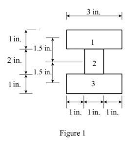
Refer to Figure 1.
Calculate the area of the cross section
Here, b is the width of the cross section and d is the depth of the cross section.
Calculate the area of the portion (1)
Substitute
Calculate the area of the portion (2)
Substitute
Calculate the moment of inertia
Calculate the moment of inertia of portion (1)
Substitute
Hence,
Calculate the moment of inertia of portion (2)
Substitute
Calculate the total moment of inertia
Substitute
Calculate the centroid (c) as shown below.
Substitute
Sketch the stress acting on the cross-section of the beam as shown in Figure 2.
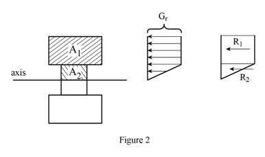
Refer Figure 2.
Calculate the area of the portion (2)
Substitute
Calculate the reaction applied to portion (1)
Substitute
Calculate the reaction applied to portion (2)
Substitute
Calculate the moment
Substitute
Calculate the stress
Substitute
Calculate the stress
Substitute
Calculate the residual stress at
Substitute
Calculate the residual stress at
Substitute
Sketch the stress distribution as shown in Figure 3.
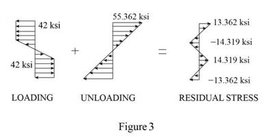
Hence, the residual stress is
(b)
Find the point where the residual stress is zero.
(b)
Answer to Problem 92P
The point where the residual stress is zero is
Explanation of Solution
Given information:
The yield stress for the beam is
The Young’s modulus for steel is
Calculation:
Consider that the residual stress is
Calculate the yield stress
Calculate the point where the residual stress is zero as shown below.
Substitute
Substitute
Therefore, the point where the residual stress is zero is
(c)
Find the radius of curvature corresponding to the permanent deformation of the bar.
(c)
Answer to Problem 92P
The radius of curvature is
Explanation of Solution
Given information:
The yield stress for the beam is
The Young’s modulus of steel is
Calculation:
Refer to part (a).
The residual stress
Calculate the radius of curvature
Calculate the point where the residual stress is zero as shown below.
Substitute
Therefore, the radius of curvature is
Want to see more full solutions like this?
Chapter 4 Solutions
Mechanics of Materials, 7th Edition


- 7. Straight rods of 0.4ft diameter and 100ft length are stored by coiling the rods inside a drum of 1.25ft in- side diameter. Assuming that the yield strength is not exceeded, determine the maximum stress in the coiled rod, the corresponding bending moment in the rod. Use E = 29 * 10°psi.arrow_forward8. The couple M acts in a vertical plane and is applied to a beam oriented ass shown. Determine the stress at point A. What would the stress be at point A if the couple M is doubled to 2.4kN – m? 40 mm 10 mm M = 1.2 kN-m C 40 mm %3D 10 mm- -70 mm→ -10 mm 1,=1.894 × 10º mm* I = 0.614 × 10º mm* Iy= +0.800 x 10º mm*arrow_forwardThe 6 × 12-in. timber beam has been strengthened by bolting to it the steel reinforcement shown. The modulus of elasticity for wood is 1.8 × 10⁶ psi and for steel, 29 × 106 psi. Knowing that the beam is bent about a horizontal axis by a couple of moment M = 458 kip·in., determine the maximum stress in the wood and in the steel. The maximum compressive stress in the block of wood is ksi (include a negative sign). The maximum tensile stress in the steel is ksi.arrow_forward
- A member having the dimensions shown is used to resist an internal bending moment of M kNm. Determine the maximum stress in the member if the moment is applied (a) about the z axis (as shown) (b) about the y axis. Sketch the stress distribution for each case. Take: M= 90 kNm A mm A= 200 mm B= 150 mm B mm Solution: The moment of inertia of the cross-section about z and y axes are I;-4 1 - AB³ 12 (10) m* I BA = (10) m*arrow_forwardA strip of steel 3 mm thick and 35 mm wide is bent round a cylindrical drum 4 mm in diameter. Determine the maximum stress set up in the strip and the bending moment which has to be applied to bend the strip to this curvature (E = 200 GPa) A hollow short cast iron column has outside and inside diameters of 250 mm and 150 mm respectively. The column is subjected to an axial load applied at a distance of 60 mm from the center of the section. (a) Calculate the maximum safe load if the allowable stresses are 110 MPa compressive and 30 MPa tensile, calculate also the position of the NA.arrow_forwardA laminated wood beam consists of six 2 x 6 in planks glued together to form a section 6 in wide by 12 in deep, as shown on the right below. If the strength of the glue in shear is 120 psi, determine the maximum uniformly distributed load w that can be applied over the full length of the beam if the beam is simply supported and has a span of 15 ft, as shown on the left below. ω 15 ft - 6 in [2 in 12 in 12 in 12 in 12 in 2 inarrow_forward
- This laboratory focusses on the bending of a simply-supported beam, as shown in the following schematic (Figure 1). W/2 Z a 6.4mm X W/2 23mm Figure 1 the loading scheme of a beam It can be shown that for this loading case, the bending moment for a ≤ x ≤ L-a is constant and equal to Wa/2. In this experiments, a = 350 mm and L = 835 mm. Loading the beam in this way, rather than loading the beam at just one point, has two main advantages: (i) it allows a strain gauge to be placed at the top of the beam and (ii) the constant bending moment area that it creates gives better strain gauge performance when stretched or compressed. 6.4mm W/2 8mm a 38.1mm W/2 indicates strain gauge 38.1mm Figure 2 the dimensions of the cross section of the beam and the position of the strain gaugesarrow_forwardA wooden beam is fabricated by nailing together three boards as shown. The boards have dimensions of b1 = 11 in., d1 = 2.1 in., b2 = 2.1 in., d2 = 10 in., b3 = 6 in., and d3 = 2.1 in. (e) If a bending moment applied about the z axis produces a tension normal stress of σx = 580 psi at the bottom of the cross section, determine the compression normal stress produced at the top of the cross section.arrow_forwardA 6 * 10-in. timber beam has been strengthened by bolting to it the steel straps shown. The modulus of elasticity is E= 1.5 *106 psi for the wood and E= 30 * 106 psi for the steel. Knowing that the beam is bent about a horizontal axis by a couple of moment 200 kip·in., determine the maximum stress in (a) the wood, (b) the steel.arrow_forward
- The rigid beam BC is supported by rods (1) and (2). The cross-sectional area of rod (1) is 10 mm2. The cross-sectional area of rod (2) is 18 mm2. For a uniformly distributed load of w = 2.4 kN/m, determine the length a so that the normal stress is the same in each rod. Assume L = 5.25 m.arrow_forwardThe rigid beam ABC is supported by a pin connection at C and by steel rod (1), which has a diameter of 12 mm. If the normal stress in rod (1) must not exceed 225 MPa, what is the maximum uniformly distributed load w that may be applied to beam ABC? Use dimensions of a = 350 mm, b = 700 mm, and c = 525.0 mm. Dot A Answer: W = ↓↓ a i 1 B W b (1) ↓↓ kN/m &arrow_forwardProblem 4: Determine the minimum height h of the beam shown in Fig. if the flexural stress exceed 20 MPa. 5 KN I= bh² 2 m mg. 2.5 kN/m ↑ Rislo 80 mm 1m ↓ 3m R₂arrow_forward
 Elements Of ElectromagneticsMechanical EngineeringISBN:9780190698614Author:Sadiku, Matthew N. O.Publisher:Oxford University Press
 Mechanics of Materials (10th Edition)Mechanical EngineeringISBN:9780134319650Author:Russell C. HibbelerPublisher:PEARSON
 Thermodynamics: An Engineering ApproachMechanical EngineeringISBN:9781259822674Author:Yunus A. Cengel Dr., Michael A. BolesPublisher:McGraw-Hill Education
 Control Systems EngineeringMechanical EngineeringISBN:9781118170519Author:Norman S. NisePublisher:WILEY
 Mechanics of Materials (MindTap Course List)Mechanical EngineeringISBN:9781337093347Author:Barry J. Goodno, James M. GerePublisher:Cengage Learning
 Engineering Mechanics: StaticsMechanical EngineeringISBN:9781118807330Author:James L. Meriam, L. G. Kraige, J. N. BoltonPublisher:WILEY