
Engineering Mechanics: Statics & Dynamics (14th Edition)
14th Edition
ISBN: 9780133915426
Author: Russell C. Hibbeler
Publisher: PEARSON
expand_more
expand_more
format_list_bulleted
Concept explainers
Videos
Textbook Question
Chapter 4.9, Problem 149P
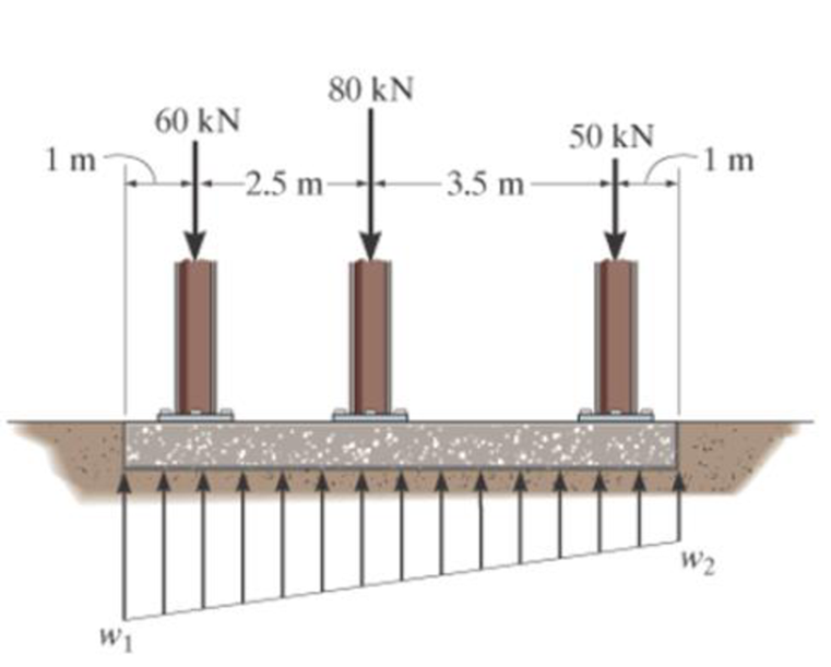
If the soil exerts a trapezoidal distribution of load on the bottom of the footing, determine the intensities w1 and w 2 of this distribution needed to support the column loadings.
Expert Solution & Answer
Want to see the full answer?
Check out a sample textbook solution
Students have asked these similar questions
The L-shaped frame is made from two segments, each of length L and flexural stiffness EI. If it is subjected to the uniform distributed load, determine the horizontal displacement of point C.
The bracket is held to the wall using three A-36 steel bolts at B, C, and D. Each bolt has a diameter of 0.5 in. and an unstretched length of 2 in. If a force of 800 lb is placed on the bracket as shown,determine the force developed in each bolt. For the calculation, assume that the bolts carry no shear; rather, the vertical force of 800 lb is supported by the toe at A. Also, assume that the wall and bracket are rigid. A greatly exaggerated deformation of the bolts is shown.
The cable carrying 60-lb loads at B and C is held in the position shown by the horizontal force P = 80 lb applied at A. Determine the following:
Find the vertical load Ay acting on the frame at support A.
Find the vertical load By acting on the frame at pin B.
Find the horizontal load Cx acting on the frame at support C.
Find the vertical load Cy acting on the frame at support C.
Find the horizontal load Ax acting on the frame at support A.
Chapter 4 Solutions
Engineering Mechanics: Statics & Dynamics (14th Edition)
Ch. 4.4 - In each case, determine the moment of the force...Ch. 4.4 - In each case, set up the determinant to find the...Ch. 4.4 - Determine the moment of the force about point O.Ch. 4.4 - Determine the moment of the force about point O.Ch. 4.4 - Determine the moment of the force about point O.Ch. 4.4 - Determine the moment of the force about point O....Ch. 4.4 - Determine the moment of the force about point O.Ch. 4.4 - Determine the moment of the force about point O.Ch. 4.4 - Determine the resultant moment produced by the...Ch. 4.4 - Determine the resultant moment produced by the...
Ch. 4.4 - Determine the resultant moment produced by the...Ch. 4.4 - Determine the moment of force F about point O....Ch. 4.4 - Prob. 11FPCh. 4.4 - Prob. 12FPCh. 4.4 - Prob. 1PCh. 4.4 - Prove the triple scalar product identity A (B C)...Ch. 4.4 - Prob. 3PCh. 4.4 - Prob. 4PCh. 4.4 - Determine the moment about point B of each of the...Ch. 4.4 - The crowbar is subjected to a vertical force of P...Ch. 4.4 - Determine the moment of each of the three forces...Ch. 4.4 - Determine the moment of each of the three forces...Ch. 4.4 - Determine the moment of each force about the bolt...Ch. 4.4 - If FB = 30 lb and FC = 45 lb, determine the...Ch. 4.4 - Prob. 11PCh. 4.4 - The towline exerts a force of P = 6 kN at the end...Ch. 4.4 - Prob. 13PCh. 4.4 - The 20-N horizontal force acts on the handle of...Ch. 4.4 - Two men exert forces of F = 80 lb and P = 50 lb on...Ch. 4.4 - Prob. 16PCh. 4.4 - Prob. 17PCh. 4.4 - The tongs are used to grip the ends of the...Ch. 4.4 - Prob. 19PCh. 4.4 - The handle of the hammer is subjected to the force...Ch. 4.4 - In order to pull out the nail at B, the force F...Ch. 4.4 - Old clocks were constructed using a fusee B to...Ch. 4.4 - The tower crane is used to hoist the 2-Mg load...Ch. 4.4 - The tower crane is used to hoist a 2-Mg load...Ch. 4.4 - If the 1500-lb boom AB, the 200-lb cage BCD, and...Ch. 4.4 - If the 1500-lb boom AB, the 200-lb cage BCD, and...Ch. 4.4 - Determine the moment of the force F about point O....Ch. 4.4 - Determine the moment of the force F about point P....Ch. 4.4 - The force F = {400i 100j 700k} lb acts at the...Ch. 4.4 - The force F = {400i 100j 700k} lb acts at the end...Ch. 4.4 - Determine the moment of the force F about point P....Ch. 4.4 - The pipe assembly is subjected to the force of F =...Ch. 4.4 - The pipe assembly is subjected to the force of F =...Ch. 4.4 - Determine the moment of the force of F = 600 N...Ch. 4.4 - Determine the smallest force F that must be...Ch. 4.4 - Determine the coordinate direction angles , , of...Ch. 4.4 - Determine the moment of force F about point O. The...Ch. 4.4 - Determine the moment of the force F about the door...Ch. 4.4 - Determine the moment of the force F about the door...Ch. 4.4 - Determine the smallest force F that must be...Ch. 4.4 - Prob. 41PCh. 4.4 - A 20-N horizontal force is applied perpendicular...Ch. 4.4 - Prob. 43PCh. 4.4 - The pipe assembly is subjected to the 80-N force....Ch. 4.4 - Prob. 45PCh. 4.4 - Prob. 46PCh. 4.4 - Prob. 47PCh. 4.4 - Prob. 48PCh. 4.4 - Prob. 49PCh. 4.4 - Prob. 50PCh. 4.4 - Using a ring collar, the 75-N force can act in the...Ch. 4.5 - In each case, determine the resultant moment of...Ch. 4.5 - Prob. 4PPCh. 4.5 - Prob. 13FPCh. 4.5 - Prob. 14FPCh. 4.5 - Determine the magnitude of the moment of the 200-N...Ch. 4.5 - Determine the magnitude of the moment of the force...Ch. 4.5 - Prob. 17FPCh. 4.5 - Determine the moment of force F about the x, the...Ch. 4.5 - The lug nut on the wheel of the automobile is to...Ch. 4.5 - Solve Prob. 4-52 if the cheater pipe AB is slipped...Ch. 4.5 - The A-frame is being hoisted into an upright...Ch. 4.5 - Prob. 55PCh. 4.5 - Determine the magnitude of the moments of the...Ch. 4.5 - Determine the moment of this force F about an axis...Ch. 4.5 - Prob. 58PCh. 4.5 - Prob. 59PCh. 4.5 - Prob. 60PCh. 4.5 - Determine the magnitude of the moment of the force...Ch. 4.5 - Determine the magnitude of the moment of the force...Ch. 4.5 - Determine the magnitude of the moment of the force...Ch. 4.5 - A horizontal force of F = {50i} N is applied...Ch. 4.5 - Prob. 65PCh. 4.5 - Prob. 66PCh. 4.6 - Determine the resultant couple moment acting on...Ch. 4.6 - Determine the resultant couple moment acting on...Ch. 4.6 - Prob. 21FPCh. 4.6 - Determine the couple moment acting on the beam.Ch. 4.6 - Determine the resultant couple moment acting on...Ch. 4.6 - Determine the couple moment acting on the pipe...Ch. 4.6 - Prob. 67PCh. 4.6 - Prob. 68PCh. 4.6 - If the resultant couple of the three couples...Ch. 4.6 - Two couples act on the beam. If F = 125 lb,...Ch. 4.6 - Two couples act on the beam. Determine the...Ch. 4.6 - Determine the magnitude of the couple forces F so...Ch. 4.6 - Prob. 73PCh. 4.6 - Prob. 74PCh. 4.6 - Prob. 75PCh. 4.6 - Determine the magnitude of F so that the resultant...Ch. 4.6 - Prob. 77PCh. 4.6 - Prob. 78PCh. 4.6 - Two couples act on the frame. If the resultant...Ch. 4.6 - Prob. 80PCh. 4.6 - Two couples act on the frame. If d = 4 ft,...Ch. 4.6 - Prob. 82PCh. 4.6 - If M1 = 180 lb ft, M2 = 90 lb ft, and M3 = 120...Ch. 4.6 - Prob. 84PCh. 4.6 - The gears are subjected to the couple moments...Ch. 4.6 - Determine the required magnitude of the couple...Ch. 4.6 - Determine the resultant couple moment of the two...Ch. 4.6 - Express the moment of the couple acting on the...Ch. 4.6 - In order to turn over the frame, a couple moment...Ch. 4.6 - Express the moment of the couple acting on the...Ch. 4.6 - If the couple moment acting on the pipe has a...Ch. 4.6 - If F = 80 N, determine the magnitude and...Ch. 4.6 - If the magnitude of the couple moment acting on...Ch. 4.6 - Express the moment of the couple acting on the rod...Ch. 4.6 - If F1 = 100 N, F2 = 120 N, and F3 = 80 N,...Ch. 4.6 - Prob. 96PCh. 4.7 - In each case, determine the x and y components of...Ch. 4.7 - F-25. Replace the leading system by an equivalent...Ch. 4.7 - F-26. Replace the loading system by an equivalent...Ch. 4.7 - Prob. 27FPCh. 4.7 - Prob. 28FPCh. 4.7 - Prob. 29FPCh. 4.7 - F-30. Replace the loading system by an equivalent...Ch. 4.7 - Replace the force system by an equivalent...Ch. 4.7 - Prob. 98PCh. 4.7 - Prob. 99PCh. 4.7 - Prob. 100PCh. 4.7 - Replace the loading system acting on the beam by...Ch. 4.7 - Prob. 102PCh. 4.7 - Prob. 103PCh. 4.7 - Prob. 104PCh. 4.7 - Replace the force system acting on the frame by an...Ch. 4.7 - Prob. 106PCh. 4.7 - Prob. 107PCh. 4.7 - Replace the force system by an equivalent...Ch. 4.7 - Prob. 109PCh. 4.7 - Prob. 110PCh. 4.7 - Prob. 111PCh. 4.7 - Prob. 112PCh. 4.8 - In each case, determine the x and y components of...Ch. 4.8 - Prob. 7PPCh. 4.8 - Replace the loading system by an equivalent...Ch. 4.8 - Prob. 32FPCh. 4.8 - Prob. 33FPCh. 4.8 - Prob. 34FPCh. 4.8 - Prob. 35FPCh. 4.8 - Prob. 36FPCh. 4.8 - Prob. 113PCh. 4.8 - Prob. 114PCh. 4.8 - Prob. 115PCh. 4.8 - Prob. 116PCh. 4.8 - Replace the loading acting on the beam by a single...Ch. 4.8 - Prob. 118PCh. 4.8 - Prob. 119PCh. 4.8 - Prob. 120PCh. 4.8 - Prob. 121PCh. 4.8 - Prob. 122PCh. 4.8 - Prob. 123PCh. 4.8 - Prob. 124PCh. 4.8 - Prob. 125PCh. 4.8 - Replace the force and couple system acting on the...Ch. 4.8 - If FA = 7 kN and FB = 5 kN, represent the force...Ch. 4.8 - Determine the magnitudes of FA and FB so that the...Ch. 4.8 - Prob. 129PCh. 4.8 - Prob. 130PCh. 4.8 - Prob. 131PCh. 4.8 - If FA= 40 kN and FB = 35 kN, determine the...Ch. 4.8 - If the resultant force is required to act at the...Ch. 4.8 - Prob. 134PCh. 4.8 - Replace the force system by a wrench and specify...Ch. 4.8 - Prob. 136PCh. 4.8 - Replace the three forces acting on the plate by a...Ch. 4.9 - Determine the resultant force and specify where it...Ch. 4.9 - Prob. 38FPCh. 4.9 - Prob. 39FPCh. 4.9 - Determine the resultant force and specify where it...Ch. 4.9 - Prob. 41FPCh. 4.9 - Prob. 42FPCh. 4.9 - Replace the loading by an equivalent resultant...Ch. 4.9 - Replace the distributed loading with an equivalent...Ch. 4.9 - Prob. 140PCh. 4.9 - Prob. 141PCh. 4.9 - Replace the distributed loading by an equivalent...Ch. 4.9 - Replace this loading by an equivalent resultant...Ch. 4.9 - The distribution of soil loading on the bottom of...Ch. 4.9 - Replace the loading by an equivalent resultant...Ch. 4.9 - Replace the distributed loading by an equivalent...Ch. 4.9 - Prob. 147PCh. 4.9 - Prob. 148PCh. 4.9 - If the soil exerts a trapezoidal distribution of...Ch. 4.9 - Prob. 150PCh. 4.9 - Prob. 151PCh. 4.9 - Prob. 152PCh. 4.9 - Replace the leading by a single resultant force,...Ch. 4.9 - Prob. 154PCh. 4.9 - Replace the distributed loading by an equivalent...Ch. 4.9 - Prob. 156PCh. 4.9 - Prob. 157PCh. 4.9 - Prob. 158PCh. 4.9 - The distributed load acts on the shaft as shown....Ch. 4.9 - Replace the distributed loading with an equivalent...Ch. 4.9 - Prob. 161PCh. 4.9 - Prob. 162PCh. 4.9 - Prob. 1RPCh. 4.9 - Replace the force F having a magnitude of F = 50...Ch. 4.9 - Prob. 3RPCh. 4.9 - Prob. 4RPCh. 4.9 - Prob. 5RPCh. 4.9 - Prob. 6RPCh. 4.9 - Prob. 7RPCh. 4.9 - Prob. 8RP
Knowledge Booster


Learn more about
Need a deep-dive on the concept behind this application? Look no further. Learn more about this topic, mechanical-engineering and related others by exploring similar questions and additional content below.Similar questions
- Assuming the reactions in the support as positive, I planted the sum of forces in x, positive towards the right. For each load, place the "+" or "-" sign as appropriate, or N / A, if the load does not apply in the sum. ΣFx = 0 RAx RAy MA 5 6 7 =0arrow_forwardQ1: The pad footing is used to support the axial loads 8000 lb and bending moment 2000 Ib. ft . Determine the intensities W1 and W2 of the distributed loading acting on the base of footing for equilibrium. - 1.2 in - 1.2 in - Steel Column 8000 lb 1 in - FIXED CONNECTION 2000 Ib.ft, BASE PLATE RC Footing W2 W1 40 inarrow_forwardThe bracket is held to the wall using three A-36 steel bolts at B, C, and D. Each bolt has a diameter of 0.5 in. and an unstretched length of 2 in. If a force of 800 lb is placed on the bracket as shown, determine the force developed in each bolt. For the calculation, assume that the bolts carry no shear; rather, the vertical force of 800 lb is supported by the toe at A. Also, assume that the wall and bracket are rigid. A greatly exaggerated deformation of the bolts is shown.arrow_forward
- The 460-kg uniform beam is subjected to the three external loads shown. Compute the reactions at the support point O. The x-y plane is vertical. Positive values are to the right, up, and counterclockwise. 0 1.2 m Answers: Ox Oy = i Mo= i i A 6.1 KN 1.6 m 19 kN.m B kN kN 1.6 m kN-m 20 C 2.7 KN -1xarrow_forwardRailroad ties must be designed to resist large shear loadings. If the tie is subjected to the 34-kip rail loadings and an assumed uniformly distributed ground reaction, determine the intensity w for equilibrium, and calculate themaximum shear stress in the tie at section a–a, which is located just to the left of the rail.arrow_forwardThe 20 mm diameter steel shaft AB is attached into the rigid wall at B and supported by a smooth bearing at A. The lever AC is welded to the end of the shaft. If the downward force P will produce a 50 mm vertical displacement at the free end of lever AC, determine the force P if G = 83 GPa.arrow_forward
- Determine the internal resultants FG, VG, and MG on the cross-section at G of the horizontal frame member. The uniformly distributed load on member AC has a magnitude w0=220 lb/ft. (See the inset for a definition of the resultants.)arrow_forwardThe boom DF at the job crane and the column DE have a uniform weight of sw N/m. If the hoist and load weight P N, determine the resultant internal loading in the crane on cross-section through points A, B and C. h2 L1=1 m L2=2 m L3=1 m h1=1 m h2=1.3 m h1 P=540 N Sw=18 N/m D E B L1 L2 A L3 P Farrow_forwardThe rigid beam is supported by three 25-mm diameter A-36 steel rods. If the beam supports the force of P=230 kN, determine the force developed in each rod. Consider the steel to be an elastic perfectly plastic material. Complete solution if possible.arrow_forward
- Determine the resultant internal loadings acting on the cross section at B for the piping system fixed at the point A with a mass of 12 kg/m. Neglect the weight of the wrench CD. 200 mm 400 mm 300 mm B 1000 N 60 NA 150 mm A 60 N 150 mm D Include in your answer: Free body diagram (FDB) Static equilibrium equationsarrow_forward5 - The ring supports the 1000-N load and is held in position by the two cables attached to vertical walls . Find the tensions T1 and T2 by at least two different ways . 1C00 Narrow_forwardThe way to the column where the loading status is seen determine the P load required for the 5 mm horizontal displacement of the C midpoint and the maximum shear stress that this P load will generate. b=750mm a=50mm t=4mm e=48mm E(modulus of elasticity)=70GPAarrow_forward
arrow_back_ios
SEE MORE QUESTIONS
arrow_forward_ios
Recommended textbooks for you
 Elements Of ElectromagneticsMechanical EngineeringISBN:9780190698614Author:Sadiku, Matthew N. O.Publisher:Oxford University Press
 Mechanics of Materials (10th Edition)Mechanical EngineeringISBN:9780134319650Author:Russell C. HibbelerPublisher:PEARSON
 Thermodynamics: An Engineering ApproachMechanical EngineeringISBN:9781259822674Author:Yunus A. Cengel Dr., Michael A. BolesPublisher:McGraw-Hill Education
 Control Systems EngineeringMechanical EngineeringISBN:9781118170519Author:Norman S. NisePublisher:WILEY
 Mechanics of Materials (MindTap Course List)Mechanical EngineeringISBN:9781337093347Author:Barry J. Goodno, James M. GerePublisher:Cengage Learning
 Engineering Mechanics: StaticsMechanical EngineeringISBN:9781118807330Author:James L. Meriam, L. G. Kraige, J. N. BoltonPublisher:WILEY
Elements Of Electromagnetics
Mechanical Engineering
ISBN:9780190698614
Author:Sadiku, Matthew N. O.
Publisher:Oxford University Press
Mechanics of Materials (10th Edition)
Mechanical Engineering
ISBN:9780134319650
Author:Russell C. Hibbeler
Publisher:PEARSON
Thermodynamics: An Engineering Approach
Mechanical Engineering
ISBN:9781259822674
Author:Yunus A. Cengel Dr., Michael A. Boles
Publisher:McGraw-Hill Education
Control Systems Engineering
Mechanical Engineering
ISBN:9781118170519
Author:Norman S. Nise
Publisher:WILEY
Mechanics of Materials (MindTap Course List)
Mechanical Engineering
ISBN:9781337093347
Author:Barry J. Goodno, James M. Gere
Publisher:Cengage Learning
Engineering Mechanics: Statics
Mechanical Engineering
ISBN:9781118807330
Author:James L. Meriam, L. G. Kraige, J. N. Bolton
Publisher:WILEY
EVERYTHING on Axial Loading Normal Stress in 10 MINUTES - Mechanics of Materials; Author: Less Boring Lectures;https://www.youtube.com/watch?v=jQ-fNqZWrNg;License: Standard YouTube License, CC-BY