
Concept explainers
Videos
For
Determine the
a. Current
b. Voltage
c. lime required for
(a)
The value of the current
Answer to Problem 5.34HP
The value of the current
Explanation of Solution
Calculation:
The conversion from
The conversion from
The conversion from
The conversion from
The conversion from
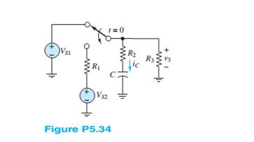
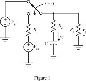
The given diagram is shown in Figure 1
For time
The required diagram is shown in Figure 2
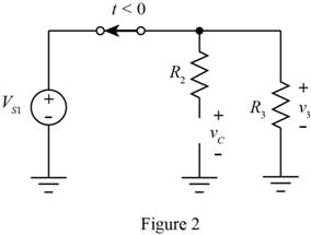
From above circuit, the value of the voltage across the capacitor terminals for time
Substitute
From the above circuit,the expression for the value of the current through the capacitor for time
For time
Mark the values and redraw the circuit for the time
The required diagram is shown in Figure 3
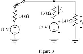
Apply KVL at the node
The expression for the current through the capacitor for time
Substitute
For time
The required diagram is shown in Figure 4
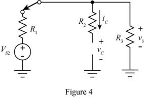
From the above circuit, the expression for the value of the current through the for the time
The expression for the voltage across the capacitor for the time
Substitute
To calculate the Thevenin equivalent resistance for the circuit open circuit the capacitor terminals, short circuit the voltage source and redraw the circuit.
The required diagram is shown in Figure 5
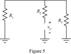
From above figure the expression to calculate the time constant of the circuit is given by,
Substitute
The expression for the complete solution for the current
Substitute
Conclusion:
Therefore, thevalue of the current
(b)
The value of voltage
Answer to Problem 5.34HP
Thevalue of the voltage
Explanation of Solution
Calculation:
The expression for the value of the voltage
Conclusion:
Therefore, the value of the voltage
(c)
The time required for
Answer to Problem 5.34HP
Thetime required for
Explanation of Solution
Calculation:
The expression for the current through the capacitor for time
Substitute
Substitute
The expression for the current
Substitute
Substitute
Substitute
Conclusion:
Therefore, the time required for
Want to see more full solutions like this?
Chapter 5 Solutions
Principles and Applications of Electrical Engineering


- =7 Determine the current through the capacitor just before and just after the switch is closed in Figure P5.37. Assume steady-state conditions for t < 0. V = 12 V C = 150 µF R = 400 m2 R2 = 2.2 k2 t = 0 R1 + SI +)arrow_forward6 Determine the voltage across the inductor just before and just after the switch is changed in Figure P5.26. Assume steady-state conditions exist for t < 0. Vs = 12 V R, = 0.7 2 R = 22 k2 L= 100 mH 1=0 R, R1arrow_forward2 At t < 0, the circuit shown in Figure P5.22 is at steady state. The switch is changed as shown at t = 0. Vsi = 35 V C = 11 µF Vsz = 130 V R = 17 k2 R2 = 7 k2 R = 23 k2 Determine at t = 0+ the initial current through R just after the switch is changed. 1= 0 R3 Vs1 Vs2arrow_forward
- 8 For t > 0, the circuit shown in Figure P5.22 is at steady state. The switch is changed as shown at t = 0. Vsi = 35 V C = 11 µF Vsz = 130 V R = 17 k2 R = 7 k2 R = 23 k2 Determine the time constant of the circuit for t> 0.arrow_forwardDescribe the steady-state similarities and differences of DC and AC circuits with purelyresistive elementsarrow_forwardDetermine v(t), the voltage across the 40 ohm resistor in the circuit in Figure P 5.3-7arrow_forward
- 1 Just before the switch is opened at t = 0, the current through the inductor is 1.70 mA in the direction shown in Figure P5.21. Did steady-state conditions exist just before the switch was opened? L= 0.9 mH Vs = 12 V R = 6 k2 R2 = 6 k2 R = 3 k2 t = 0 R2 R1 L R3{Va3 V83arrow_forwardGiven circuit below, use superposition to find voltage across the capacitor, vclt). Frequency is 100 Hz. 6kn 4kn reee zkn O SmA <45 Vc (t) DC a) Given circuit below and switch ciosed for long time, what is the value of Vc? 5mA 3 luk bị At0, switch is opened. Write a mathematical expression for Velt) after opening of the switch. Evaluate this voltage at te10 ms. Attach File Browse Local Fies rowie Conent Cotection 74°Farrow_forwardWhat impedance vector (0- j15) Ohms represents:A. A pure resistance. C. A pure capacitance.B. A pure inductance. D. An inductance combined with a capacitance.arrow_forward
- The time taken by the series RL circuit having an inductance of 0.6 H and resistance of 30 Ohms to reach a steady-state value.arrow_forward1 Find v for t > O in the circuit of Figure P5.81 if the circuit is in steady state at t = 0-. t= 0 32 ww 12 V 0.8 HE 4 V 1/4 Farrow_forward5.1 Find V, in the circuit shown in Figure P5.1. FIGURE P5.1 0.5 V Vs R₁ www 1 ΚΩ ti + U₁ R₂ 6 ΚΩ OUTarrow_forward
 Introductory Circuit Analysis (13th Edition)Electrical EngineeringISBN:9780133923605Author:Robert L. BoylestadPublisher:PEARSON
 Delmar's Standard Textbook Of ElectricityElectrical EngineeringISBN:9781337900348Author:Stephen L. HermanPublisher:Cengage Learning
 Programmable Logic ControllersElectrical EngineeringISBN:9780073373843Author:Frank D. PetruzellaPublisher:McGraw-Hill Education
 Fundamentals of Electric CircuitsElectrical EngineeringISBN:9780078028229Author:Charles K Alexander, Matthew SadikuPublisher:McGraw-Hill Education
 Electric Circuits. (11th Edition)Electrical EngineeringISBN:9780134746968Author:James W. Nilsson, Susan RiedelPublisher:PEARSON
 Engineering ElectromagneticsElectrical EngineeringISBN:9780078028151Author:Hayt, William H. (william Hart), Jr, BUCK, John A.Publisher:Mcgraw-hill Education,