
Concept explainers
Plot the shear diagram, bending moment diagram, axial force diagram, and the qualitative deflected shape of the frame.
Explanation of Solution
Write the condition for static instability, determinacy and indeterminacy of plane frames as follows:
Here, number of members is m, number of external reactions is r, the number of joints is j, and the number of elastic hinges is
Find the degree of static indeterminacy (i) using the equation;
Refer to the Figure in the question;
The number of members (m) is 3.
The number of external reactions (r) is 3.
The number of joints (j) is 4.
The number of elastic hinges
Substitute the values in Equation (2);
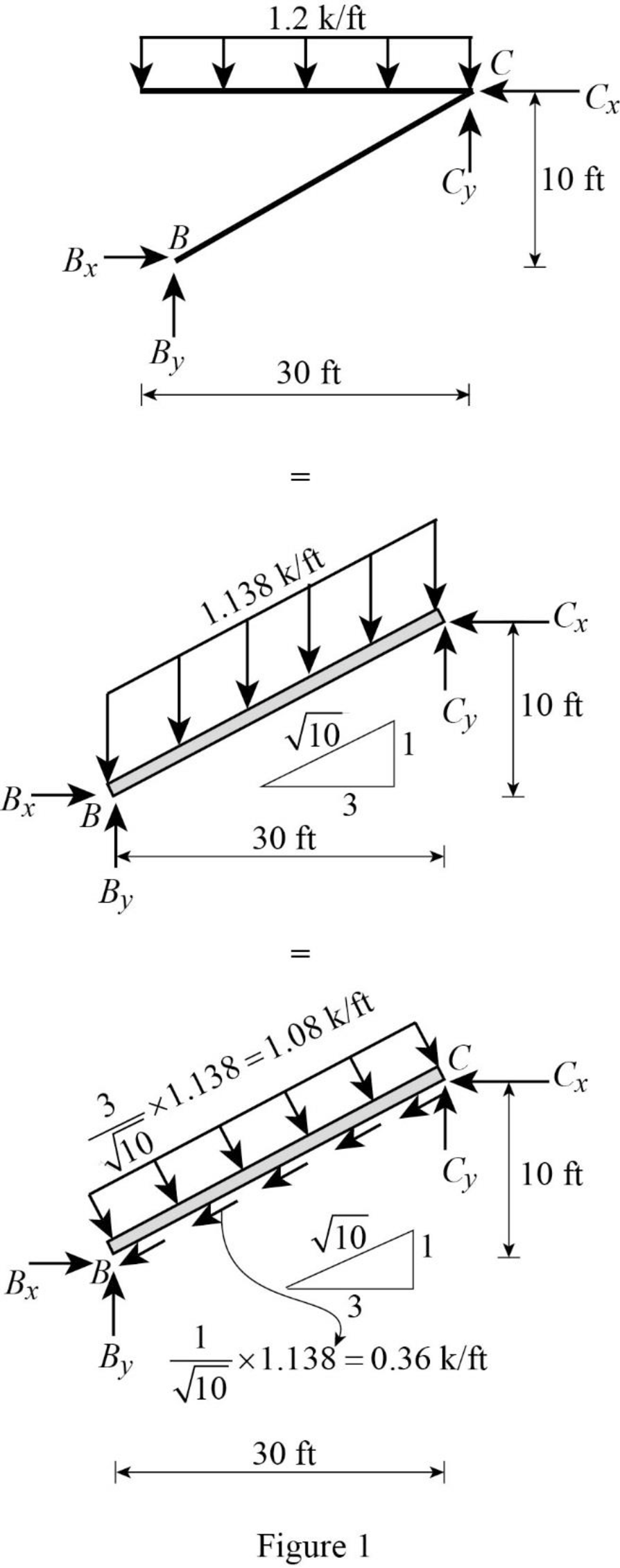
Show the equivalence of uniformly distributed load as in Figure 1.
Show the free-body diagram of the entire frame as in Figure 2.
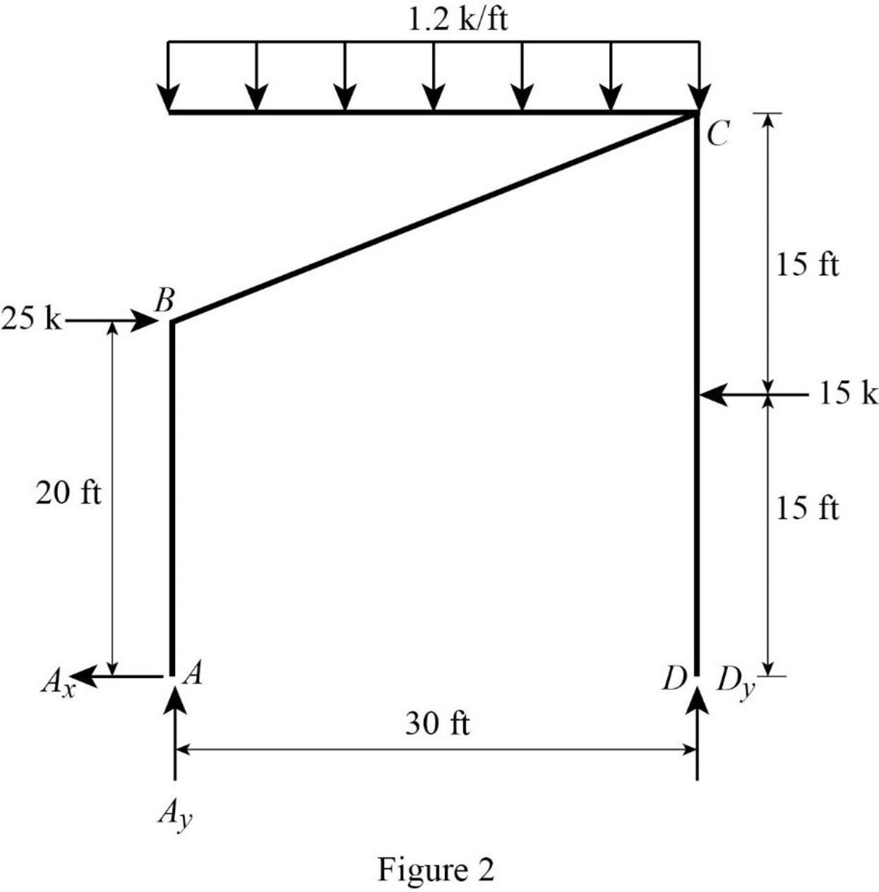
Find the horizontal reaction at point A by resolving the horizontal component of forces.
Find the vertical reaction at point D by taking moment about point A.
Find the vertical reaction at point A by resolving the vertical component of forces.
Show the free-body diagram of the members and joints of the entire frame as in Figure 3.
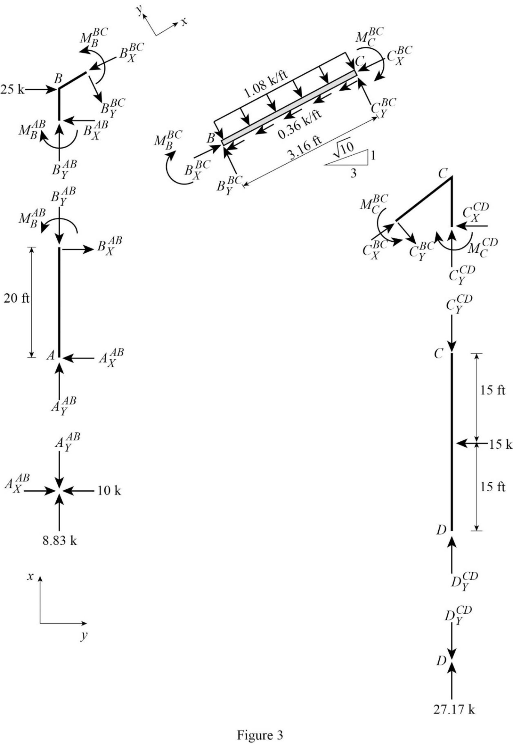
Consider point A:
Resolve the vertical component of forces.
Resolve the horizontal component of forces.
Consider the member AB:
Resolve the vertical component of forces.
Take moment about the point B.
Consider the point D:
Resolve the vertical component of forces.
Consider the member CD:
Resolve the vertical component of forces.
Take moment about the point C.
Resolve the horizontal component of forces.
Consider the point C:
Resolve the vertical component of forces.
Resolve the horizontal component of forces.
Take moment about the point C.
Consider the section BC:
Resolve the vertical component of forces.
Resolve the horizontal component of forces.
Take moment about point B:
Plot the moment end forces of the frame as in Figure 4.
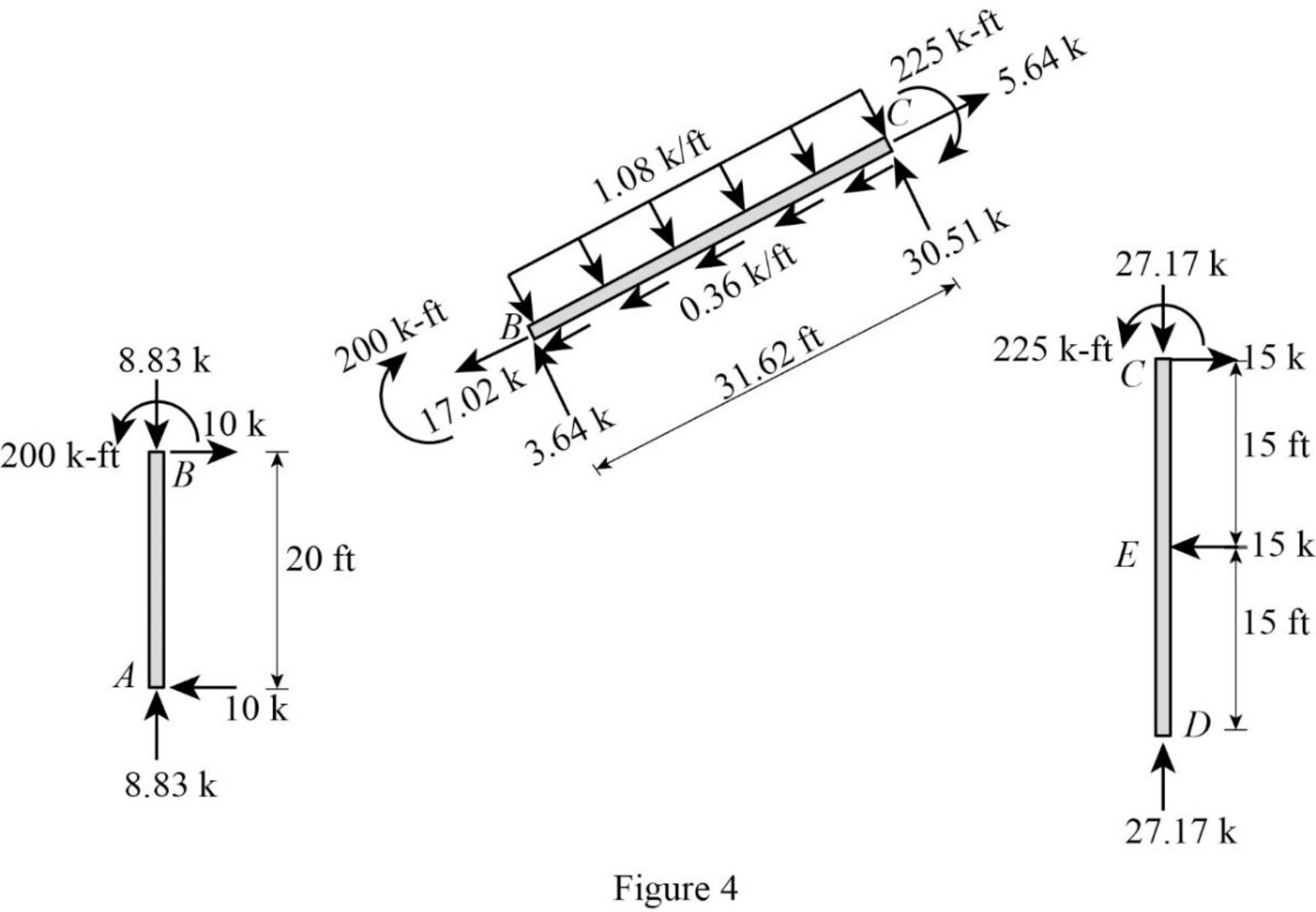
Refer to the moment end force diagram plot the shear diagram, bending moment diagram, and the axial force diagrams.
Plot the shear force diagram as in Figure 5.
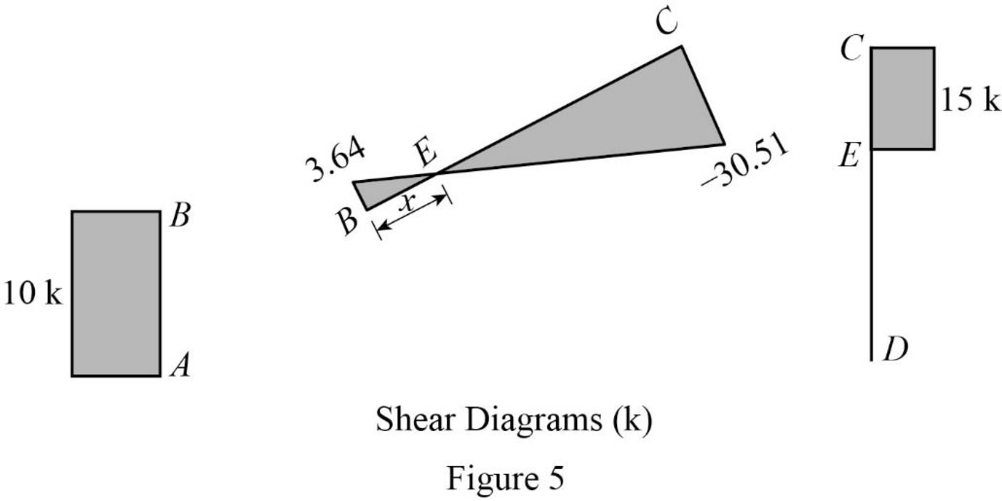
The maximum bending moment occurs where the shear force changes sign.
Consider the section BEC, use the similar triangle concept.
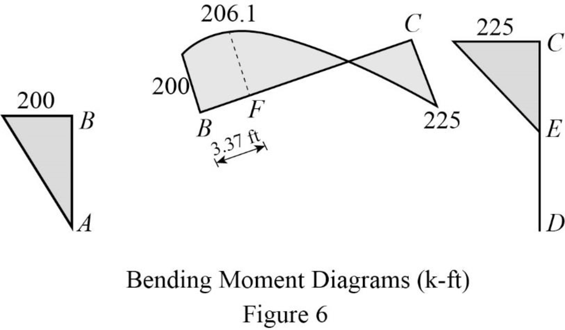
Plot the bending moment diagram as in Figure 6.
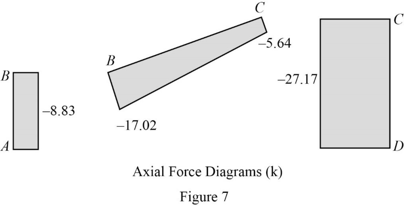
Plot the axial force diagram as in Figure 7.
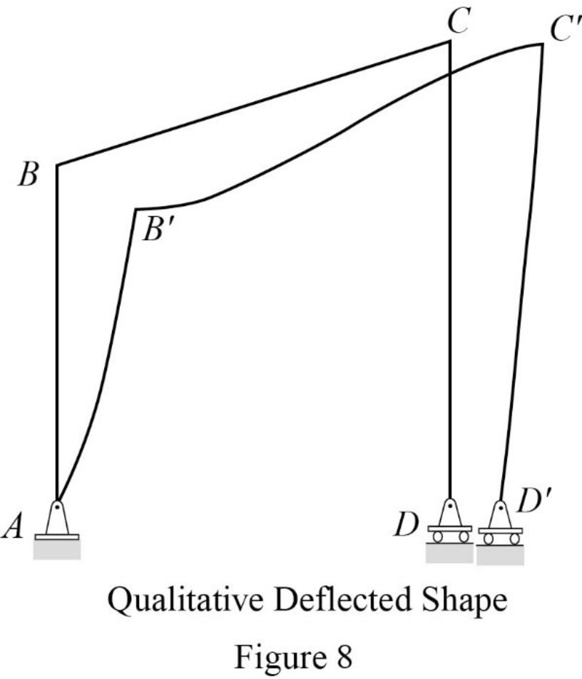
Plot the qualitative deflected shape as in Figure 8.
Want to see more full solutions like this?
Chapter 5 Solutions
Structural Analysis


- Q. I Determine the slope at the supports of the beam shown in Fig. I using the moment-area method. Also, determine the deflections at B. E = 29,000 ksi and I = 1,000 in.*. 40 k 60 k Fig. 1 B 10 ft 1 10 ft 21 10 f 1arrow_forwardwhy is the triangle part curved in the shear moment diagramarrow_forwarddraw the shear and bending moment diagrams and the qualitative deflected shape for the beam shown. number 2 in the imagearrow_forward
- Q. 3 Determine the deflections at B and C for the beam shown in Fig. 2 using the conjugate beam method. Also, determine the slope at D. El is constant. E = 20,000ksi and I = 31500 in.¹. 1.5 k/ft H -6 ft 30 k B +4ft- C -5 ft- Fig. 2arrow_forwardThe truss shown in Fig.3 is supported by a roller at C and a hinge at D. Use Castigliano's theorem to calculate the horizontal deflection for point B. E-200 B. kN/mm² and A-800 mm² for all members. s) 15 kN 2 m 20 KN B Th 2 m Fig.3arrow_forwardFor the shown frame: 1. Calculate support reactions. 2. Draw B.M.D., S.F.D. and N.F.D. 3. Use the Virtual Work Method to calculate: (a) Horizontal deflection of Point H, (b) Right side rotation of Point F, due to the given loads. El is 15x105 kip.ft2. Axial deformations are negligible. 20 kip | 3 kip/ft A D H 5 ft 50 kip.... 5 ft 6 ft 15 ft E A 4 ft 30 kip 7.5 ft F 7.5 ft 7.5 ft G B Tim 6 ft ..... 40 kip N 6 ft 8 ftarrow_forward
- Q. 2 Determine the deflections at B and C for the beam shown in Fig. 2 using the moment- area method. Also, determine the slope at D. EI is constant. E = 20,000 ksi and I = 31500 in.4. 1.5 k/ft 30 k Fig. 2 A В 6 ft 4 ft- 5 ftarrow_forwardShow shear and moment diagram pleasearrow_forward7.34 Use the graphical method to construct the shear-force and bending-moment diagrams for the beam shown. Label all significant points on each diagram and identify the maximum moments along with their respective locations. Additionally: (a) Determine V and M in the beam at a point located 0.75 m to the right of B. (b) Determine V and M in the beam at a point 15 kN 18 kN 40 kN/m 3 m 6 m 4 m located 1.25 m to the left of C. Fig. P7.34arrow_forward
- 4- Determine the vertical and horizontal deflections at joint B of the truss shown using the virtual work method. 3 m m 100 kN -50 kN m EA constant E = 70 GPa A = 1,000 mm²arrow_forward6.14 through 6.17 use the moment area method to determine the slopes and deflections at points B and C of the beam shown.arrow_forwardQ2: The effect or two forces FA,FB is (5 KN) and acting along u axis , determine the value of FB by parallelogram method (nun perpendicular coordinate) FA-3 kN -****** ************arrow_forward