
Industrial Motor Control
7th Edition
ISBN: 9781133691808
Author: Stephen Herman
Publisher: Cengage Learning
expand_more
expand_more
format_list_bulleted
Videos
Question
Chapter 64, Problem 1RQ
To determine
The diagram for the schematic symbol for the TRIAC.
Expert Solution & Answer
Explanation of Solution
The TRIAC is the device that is used to control the AC power and they can swtich the high voltage and the large current over the both the cycle of the AC power. The TRIAC is also a three terminal bidirectional device.
Consider that the PNPN junction is connected in parallel to the NPNP junction is called the TRIAC.
The schematic symbol for the TRIAC is shown in Figure below.
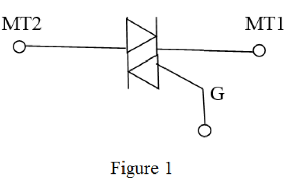
The symbol for triac is shown in Figure 1
Want to see more full solutions like this?
Subscribe now to access step-by-step solutions to millions of textbook problems written by subject matter experts!
Students have asked these similar questions
Specify all datum lines and create FBD
How many DOF do the following have in their normal environment ?
a. submerged submarineb. An earth-orbiting satellitec. A surface shipd. A motorcyclee. The print head in a 9-pin dot matrix computer printerf. The pen in an XY plotter
3 Write the names of the following connection
types and the elements used.
Knowledge Booster


Learn more about
Need a deep-dive on the concept behind this application? Look no further. Learn more about this topic, mechanical-engineering and related others by exploring similar questions and additional content below.Similar questions
- Supposing a programmer, using absolute mode, mistakenly entered Z-3.689, when he or she intended to enter Z3.689. Describe what would happen, and how far the actual position would be from the intended position.arrow_forwardWhen programming in Boolean, what statement should be used to connect components in series?arrow_forwardWhat does the schematic symbol below representing?arrow_forward
- QUESTION IS SOLVE ALREADY DRAW THE KINEMATIC DIAGRAM ONLY … Draw the kinematic diagram with graphsarrow_forwardconstruct a CNC program using G and M codes fo part drawing as shown below (take z=5 mm)arrow_forwardQuestion 11 For the kinematics linkage shown below, find the degree of freedom.arrow_forward
- 0340 030- 0100 Ø160 280 60 --030 -775 Kinematic Diagram of a Slider-Crank Mechanism (Figure 1-01) A. Draw the line diagram B. Compute the degree of freedom C. Label the parts -160- 020 065 $10 5 65 5arrow_forwardCreate a fourbar connection with an output link that can make complete circles. crank - 20 cm long ground link - 10 cm long output link - 40 cm longarrow_forward10) Get a kinematic diagram (schematic view) equivalent to the following mechanism and its degree of freedom.arrow_forward
arrow_back_ios
SEE MORE QUESTIONS
arrow_forward_ios
Recommended textbooks for you
 Understanding Motor ControlsMechanical EngineeringISBN:9781337798686Author:Stephen L. HermanPublisher:Delmar Cengage Learning
 Precision Machining Technology (MindTap Course Li...Mechanical EngineeringISBN:9781285444543Author:Peter J. Hoffman, Eric S. Hopewell, Brian JanesPublisher:Cengage Learning
Understanding Motor Controls
Mechanical Engineering
ISBN:9781337798686
Author:Stephen L. Herman
Publisher:Delmar Cengage Learning
Precision Machining Technology (MindTap Course Li...
Mechanical Engineering
ISBN:9781285444543
Author:Peter J. Hoffman, Eric S. Hopewell, Brian Janes
Publisher:Cengage Learning
Material Science, Phase Diagrams, Part 1; Author: Welt der Werkstoffe;https://www.youtube.com/watch?v=G83ZaoB3XCc;License: Standard Youtube License