
Videos
6.65 through 6.68 An extruded beam has the cross section shown. Determine (a) the location of the shear center O, (b) the distribution of the shearing stresses caused by the vertical shearing force V shown applied at O.
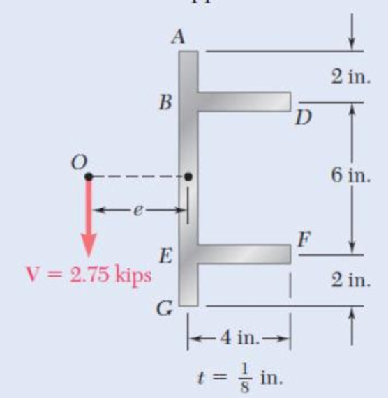
Fig. p6.67
(a)
Find the location of the shear center O.
Answer to Problem 68P
The location of the shear center O is
Explanation of Solution
Calculation:
Calculate the moment of inertia as shown below.
Here, b is the width of the section, d is the height of the section, A is the area of the beam, and
Calculate the moment of inertia for whole section as shown below.
Calculate the forces acting along the member as shown below.
Here,
Sketch the cross section of flange as shown in Figure 1.
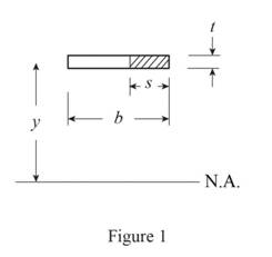
Refer to Figure 1.
Calculate the first moment of area as shown below.
Calculate the first moment of area for AB as shown below.
Calculate the horizontal shear per unit length as shown below.
Here, V is the vertical shear.
Substitute
Calculate the force
Substitute
For flange AB and flange HJ:
Substitute
For flange DE and flange FG:
Substitute
Sketch the shear flow as shown in Figure 2.
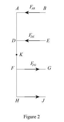
Refer to Figure 2.
Calculate the eccentricity as shown below.
Substitute
Therefore, the location of the shear center O is
(b)
Find the distribution of the shearing stresses caused by the vertical shearing force.
Answer to Problem 68P
The shearing stress at point B, E, G, and J is
The shearing stress at point A and H is
The shearing stress at point just above D and just below F is
The shearing stress at point just to the right of D and just to the right of F is
The shearing stress at point just below D and just above F is
The shearing stress at point K is
Explanation of Solution
Given information:
The vertical shear is
Calculation:
Refer to part (a).
The moment of inertia
Calculate the shear stress as shown below.
At point B, E, G, and J:
Calculate the first moment of area as shown below.
Hence, the shearing stress at point B, E, G, and J is
At point A and H:
Calculate the first moment of area as shown below.
The thickness of the section is
Calculate the shear stress as shown below.
Substitute
Hence, the shearing stress at point A and H is
At point just above D and just below F:
Calculate the first moment of area as shown below.
The thickness of the section is
Calculate the shear stress as shown below.
Substitute
Hence, the shearing stress at point just above D and just below F is
At point just to the right of D and just to the right of F:
Calculate the first moment of area as shown below.
The thickness of the section is
Calculate the shear stress as shown below.
Substitute
Hence, the shearing stress at point just to the right of D and just to the right of F is
At point just below D and just above F:
Calculate the first moment of area as shown below.
The thickness of the section is
Calculate the shear stress as shown below.
Substitute
Hence, the shearing stress at point just below D and just above F is
At point just below D and just above F:
Calculate the first moment of area as shown below.
The thickness of the section is
Calculate the shear stress as shown below.
Substitute
Hence, the shearing stress at point just below D and just above F is
At point K:
Calculate the first moment of area as shown below.
The thickness of the section is
Calculate the shear stress as shown below.
Substitute
Therefore, the shearing stress at point K is
Want to see more full solutions like this?
Chapter 6 Solutions
Mechanics of Materials, 7th Edition


- A timber beam AB of length L and rectangular cross section carries a single concentrated load P at its midpoint C. (a) Show that the ratio Tm/ m of the maximum values of the shearing and normal stresses in the beam is equal to h/2L, where h and L are, respectively, the depth and the length of the beam. (b) Determine the depth h and the width b of the beam, knowing that L = 2 m, P = 40 kN, 7m = 960 kPa, and om = 12 MPa.arrow_forwardI need help solving Problem 5.30 5.29) Knowing that P = Q = 480 N, determine (a) the distance a for which the absolute value of the bending moment in the beam is as small as possible, (b) the corresponding maximum normal stress due to bending. (See hint of Prob. 5.27. 5.30) Solve Prob. 5.29, assuming that P = 480 N and Q = 320 N.arrow_forward2. Link AB, of width b 5 50 mm and thickness t 5 6 mm, is used to support the end of a horizontal beam. Knowing that the average normal stress in the link is 2140 MPa, and that the average shearing stress in each of the two pins is 80 MPa, determine (a) the diameter d of the pins, (b) the average bearing stress in the link.arrow_forward
- Homework A timber beam AB of length L and rectangular cross section carries a single concentrated load P at its midpoint C. (a) Show that the ratio Tm/Tm of the maximum values of the shearing and normal stresses in the beam is equal to h/2L, where h and L are, respectively, the depth and the length of the beam. (b) Determine the depth h and the width b of the beam, knowing that L = 2 m, P = 40 KN, T, = 960 kPa, and om = 12 MPa. m · L/2 C - L/2· A Вarrow_forwardHomework A timber beam AB of length L and rectangular cross section carries a single concentrated load P at its midpoint C. (a) Show that the ratio Tm/Tm of the maximum values of the shearing and normal stresses in the beam is equal to h/2L, where h and L are, respectively, the depth and the length of the beam. (b) Determine the depth h and the width b of the beam, knowing that L = 2 m, P = 40 kN, 7m = 960 kPa, and om = 12 MPa. |P L/2 - - L/2· A Вarrow_forward(B) Q: The cantilever beam shown below has a circular cross section of 50mm outer diameter. Portion AB of the beam is hollow, with an inner diameter of 35mm. If the allowable bending stress is 140 MPa, determine (1) the largest allowable uniformly distributed load (w) that can be applied to the beam; (2) the bending stress at a point that is 7 mm below the top of the beam at section D. 50 mm W D B O! 35 mm A - 750 mm 250 mmarrow_forward
- Homework A timber beam AB of length L and rectangular cross section carries a single concentrated load P at its midpoint C. (a) Show that the ratio Tm/0, of the maximum values of the shearing and normal stresses in the beam is equal to h/2L, where h and L are, respectively, the depth and the length of the beam. (b) Determine the depth h and the width b of the beam, knowing that L = 2 m, P = 40 kN, 7,m = 960 kPa, and om 12 MPa. %3D L/2- - L/2 16|- Вarrow_forwardDetermine (a) the distance a for which the maximum absolute value of the bending moment in the beam is as small as possible, (b) the corresponding maximum normal stress due to bending.arrow_forwardSolve Prob. 7.43 knowing that P= 3wa.(Reference to Problem 7.43):Assuming the upward reaction of the ground on beam AB to be uniformly distributed and knowing that P= wa, (a) draw the shear and bending-moment diagrams, (b) determine the maximum absolute values of the shear and bending moment.arrow_forward
- An elastomeric bearing (G=130 psi) is used to support a bridge girder as shown to provide flexibility during earthquakes. The beam must not displace more than 38 in. when a 5-kip lateral load is applied as shown. Knowing that the maximum allowable shearing stress is 60 psi, determine (a) the smallest allowable dimension b, (b) the smallest required thickness a.arrow_forwardDetermine (a) the distance a for which the absolute value of the bending moment in the beam is as small as possible, (b) the corresponding moximum normal stress due to bending.arrow_forward(14) A beam of I-section is 2 in. wide and 4 in. deep with all sections 1/2 in. thick. It is supported at points 5ft. apart, and carries a concentrated load of 400 lb at a distance of 2ft from the left support. (a) Determine the horizontal shear in the vertical section just to the left of the load and at distances of 0, 1, and 2 in. from the neutral axis. (b) Determine the horizontal shear in the vertical section just to the right of the left support and at distances 0, 1, and 1 ½ in. from the neutral axis.arrow_forward
 Elements Of ElectromagneticsMechanical EngineeringISBN:9780190698614Author:Sadiku, Matthew N. O.Publisher:Oxford University Press
 Mechanics of Materials (10th Edition)Mechanical EngineeringISBN:9780134319650Author:Russell C. HibbelerPublisher:PEARSON
 Thermodynamics: An Engineering ApproachMechanical EngineeringISBN:9781259822674Author:Yunus A. Cengel Dr., Michael A. BolesPublisher:McGraw-Hill Education
 Control Systems EngineeringMechanical EngineeringISBN:9781118170519Author:Norman S. NisePublisher:WILEY
 Mechanics of Materials (MindTap Course List)Mechanical EngineeringISBN:9781337093347Author:Barry J. Goodno, James M. GerePublisher:Cengage Learning
 Engineering Mechanics: StaticsMechanical EngineeringISBN:9781118807330Author:James L. Meriam, L. G. Kraige, J. N. BoltonPublisher:WILEY