
Concept explainers
Find the hydraulic uplift force at the base of the hydraulic structure per meter length.
Answer to Problem 8.5P
The hydraulic uplift force at the base of the hydraulic structure per meter length is
Explanation of Solution
Given information:
The hydraulic conductivity of the permeable soil layer k is
The head difference between the upstream and downstream H is 10 m.
The height of the water level
The depth of permeable layer up to the tip of the hydraulic structure D is 1.67 m.
The depth of permeable layer
Calculation:
Draw the free body diagram of the flow net for the given values as in Figure 1.
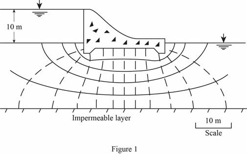
Determine the head loss for each drop using the relation.
Here,
Refer Figure 1.
The number of potential drop
Substitute 10 m for H and 12 for
Determine the pressure head at D using the relation.
Here, flow dis is the flow net distance.
Substitute 10 m for H, 3.34 m for
Determine the pressure head at E using the relation.
Substitute 10 m for H, 3.34 m for
Determine the pressure head at F using the relation.
Substitute 10 m for H, 1.67 m for D, 3.5 m for flow dis, and 0.833 for
Determine the pressure head at G using the relation.
Substitute 10 m for H, 1.67 m for D, 8.5 m for flow dis, and 0.833 for
Determine the pressure head at H using the relation.
Substitute 10 m for H, 3.34 m for
Determine the pressure head at I using the relation.
Substitute 10 m for H, 3.34 m for
Determine the hydraulic uplift force at the base of the hydraulic structure per meter length using the relation.
Here,
Take unit weight of water
Substitute
Draw the pressure head diagram as in Figure 2.
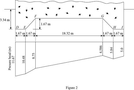
Therefore, the hydraulic uplift force at the base of the hydraulic structure per meter length is
Want to see more full solutions like this?
Chapter 8 Solutions
Principles of Geotechnical Engineering (MindTap Course List)


- Refer to Problem 8.4. Using the flow net drawn, calculate the hydraulic uplift force at the base of the hydraulic structure per meter length (measured along the axis of the structure).8.24 For the hydraulic structure shown in Figure 8.24, draw a flow net for flow through the permeable layer and calculate the seepage loss in m3/day/m.arrow_forwardWater flows at the rate of 4 x 10⁻² cm³/s through a cylindrical sand sample with a diameter of 10 cm and a coefficient of permeability of 8 x 10⁻⁴ cm/s. In Case I, the flow is in upward direction, as shown in Figure 3a. In Case II, the flow is in downward direction, as shown in Figure 3b. For each case: a). The total head loss through the sand. b). The total stress, the effective stress and the PWP at points A, B and C if the soil has a saturated unit weight of 19 kN/m³. a). Case I 9 cm 12 cm 12 cm ▼ C B A D = 10 cm 9 cm 12 cm 12 cm b). Case II Figure 3. Seepage through soil ▼ с B A ? D = 10 cmarrow_forwarda. For Figure 2 below, calculate the effective hydraulic conductivity for flow parallel and perpendicular to layering. Show your work. Explain the difference in values. Figure 2 sand layer; K = 1 m/d; thickness = 5 d 10.5 m clay layer; K = 0.000001 m/d; thickness = 0.5 m sand laver: K = 1 m/d; thickness = 5 m b. Figure 3 below shows the effects of groundwater refraction, assuming that groundwater flow in the top layer is almost horizontal i.e., a = 89.8°, what is B and what can you say about the flow in the clay layer? a a K, b B K Figure 3.arrow_forward
- #18 A non isotropic soil supporting the dam as shown in the figure. The flow net has 4 flow channels and 20 equipotential drops. Coefficient of permeability of soil. Vertical coefficient of permeability: Kv = 0.002 m/day Horizontal coefficient of permeability: Kx = 0.018 m/day 12m 4marrow_forward5.Hydraulic jump occurs in a 4 m wide rectangular channel. Discharge in channel 7.5 m^3 /s, hydraulic jump upstream depth 0.2 m. Determine :the rate of energy loss due to hydraulic jump.arrow_forwardA pump well is dug through a confined aquifer having a thickness of 32 meters. The piezometric surface of the aquifer is 18 meters measured from the top impermeable layer. The first observation well is 75 feet directly west of the pump well and the second observation well is 75 feet directly north of the first observation well. Determine the hydraulic conductivity of the aquifer if it supplies a discharge of 10 liters per second and the drawdown of the observation wells are 13 feet and 23 feet.arrow_forward
- 11. A channel runs almost parallel to a river as shown in the figure. The water level in the river has an elevation of 36 m. and the elevation of the channel is 33 m. The river and channel are 600 m apart and a previous formation of the average thickness of 9 m and hydraulic conductivity of 0.80 m/hr joints them together. Compute the hydraulic gradient Compute the rate of seepage flow from the river to the channel per meter width in liters per day. If the seepage velocity is 0.048 m/day, compute the void ratio of the previous medium.arrow_forwardEXAMPLE 9.4 Refer to the flow net shown in Figure 9.11 (which is the same one as in Figure 8.8). Consider the flow element abcd, and estimate the seepage force at O per unit volume of soil in the direction of flow. 5 m Retaining wall Impervious layer d a e 0 2.59/m f Sand barrow_forward5.4 The figure shows the cross-section of a levee that is 500 m long and is underlain by a 2-m-thick permeable sand layer. It was observed that the quantity of water flowing through the sand layer into the collection ditch is 250 m³/day. What is the hydraulic conductivity of the sand layer. Ans. k = 3.125 m/day Elv. 160 m Levee Elv. 150 m 2 m Ditch 125 m Impervious Sandarrow_forward
- 9. From the figure shown: (See picture below) Cross-sectional area = 0.6m2 Hydraulic Conductivity of sand = 0.1 cm/sec What is the rate of upward seepage of water? (Answer: 360 cm3/sec) What would be the critical hydraulic gradient? (Answer: 1.12 m) What value of h to cause boiling? (Answer: 2.8 m)arrow_forwardSeepage around a retaining wall is shown in the figure below. The hydraulic conductivity of the sand is 1.8 x 10⁻⁵ cm/s. The retaining wall is 20 m long. Determine the quantity of seepage across the entire wall per dayarrow_forwardEXAMPLE 8.2 A flow net for flow around a single row of sheet piles in a permeable soil layer is shown in Figure 8.7. Given that k, = k = k = 5 x 10-³ cm/s, determine a. How high (above the ground surface) the water will rise if piezometers are placed at points a and b b. The total rate of seepage through the permeable layer per unit length c. The approximate average hydraulic gradient at c Water level Ground surface Scale 5 m 5.6 m 2.2 m Water table Flow channel 1 Flow channel 2 Flow channel 3 Impervious layer FIGURE 8.7 Flow net for seepage around a single row of sheet piles b 1/ b = 1 = 1 1 1 T 0.38arrow_forward
 Principles of Geotechnical Engineering (MindTap C...Civil EngineeringISBN:9781305970939Author:Braja M. Das, Khaled SobhanPublisher:Cengage Learning
 Principles of Foundation Engineering (MindTap Cou...Civil EngineeringISBN:9781337705028Author:Braja M. Das, Nagaratnam SivakuganPublisher:Cengage Learning
 Fundamentals of Geotechnical Engineering (MindTap...Civil EngineeringISBN:9781305635180Author:Braja M. Das, Nagaratnam SivakuganPublisher:Cengage Learning