
(a)
The design of a three-plate moment connection of a
Answer to Problem 8.6.4P
Use a
1/8-in. fillet weld on both sides of the plate.
Use a
Explanation of Solution
Given:
Service dead-load moment = 42 ft-kips
Service live-load moment = 104 ft-kips
Service dead-load beam reaction = 8 kips
Service live-load beam reaction = 21 kips
Group A bearing type bolts
E70 electrodes
A992 steel- Beam and column
A36 steel- Plate material
Calculation:
Reaction:
Moment:
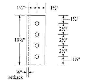
Web plate:
Neglect eccentricity.
Try 5/8-in. diameter bolts.
Assume that threads are in the plane of shear.
Shear capacity of one bolt is
Number of bolts required is
Try 4 bolts.
Determine plate thickness required for bearing. Assume that
Load resisted by each bolt =
Let
Try
Determine whether plate or beam web controls bearing. For the plate,
For the beam web,
Therefore, plate controls.
Check bearing strength assumption:
For the hole nearest the edge, minimum
Try
Therefore, use
For other bolts, minimum
Use
Therefore, use
Bearing controls over shear at each bolt location. Total strength is
Use four 5/8-in. diameter Group A bolts.

Determine plate thickness required for shear:
Shear yielding strength is
Let
Try
Check shear rupture strength:
Use hole diameter =
Check block shear:
Shear areas:
Tension area:
with an upper limit of
The nominal block shear strength is therefore 64.92 kips. The design block shear strength is
Use a
Connection of shear plate to column flange:
Use E70 electrodes
Minimum weld size, based on the plate thickness, is 1/8-in. try
Weld strength =
Base metal (plate) shear strength:
Yielding:
Rupture:
Total length required =
Use a continuous 1/8-in. fillet weld, both sides of plate.
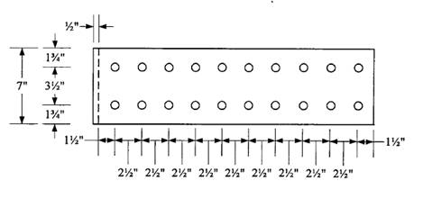
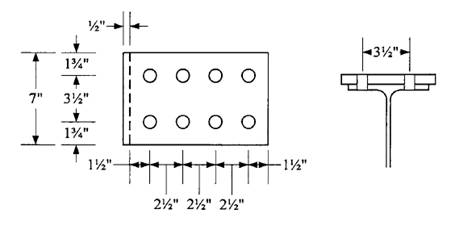
Flange plate:
From
Try 7/8-in. diameter bolts.
Assume that threads are in the plane of shear.
Number of bolts required for shear is
Try 8 bolts (4 pair)
Determine plate thickness required for bearing:
Minimum
Use
Minimum
Use
For the hole nearest the edge,
Therefore, use
For other bolts,
Therefore, use
Total connection strength =
Let
Design top flange plate as a tension connection element
Tension on gross area:
Required
Tension on net area:
Required
Try a plate width of
For gross area requirement,
For net area requirement,
Hole diameter =
Try a plate
Check compression in the bottom plate:
Assume that the plate acts as a fixed-end compression member between the end fastener and the weld. Use
For compression elements with
Therefore,
Check block shear on the plate using the dimensions and bolt layout shown.

Shear areas:
Tension area:
with an upper limit of
The nominal block shear strength is therefore 395.9 kips. The design block shear strength is
Check block shear strength of beam flange:
Transverse spacing = gauge distance = 3.5 in.
Transverse edge distance =
Longitudinal spacing and edge distance same as for plate.
Shear areas:
Tension area:
with an upper limit of
The nominal block shear strength is therefore 199.7 kips.
The design block shear strength is
Check beam for the effect of bolt holes in the tension flange:
The gross area of one flange is
The effective hole diameter is
Since
Try a smaller diameter bolt. Try ½-in. diameter bolts.
Normal shearing strength =
Number of bolts required for shear is
Try 20 bolts (10 pair)
Bearing and block shear will be satisfactory.
Check reduction in beam flange area:
Use a hole diameter =
Since
Plate length =
Conclusion:
Use a
(b)
The design of a three-plate moment connection of a
Answer to Problem 8.6.4P
Use a
1/8-in. fillet weld on both sides of the plate.
Use a
Explanation of Solution
Given:
Service dead-load moment = 42 ft-kips
Service live-load moment = 104 ft-kips
Service dead-load beam reaction = 8 kips
Service live-load beam reaction = 21 kips
Group A bearing type bolts
E70 electrodes
A992 steel- Beam and column
A36 steel- Plate material
Calculation:
Reaction:
Moment:
Web plate:
Neglect eccentricity.
Try 5/8-in. diameter bolts.
Assume that threads are in the plane of shear.
Shear capacity of one bolt is
Number of bolts required is
Try 4 bolts.
Determine plate thickness required for bearing. Assume that
Load resisted by each bolt =
Let
Try
Determine whether plate or beam web controls bearing. For the plate,
For the beam web,
Therefore, plate controls.
Check bearing strength assumption:
For the hole nearest the edge, minimum
Try
Therefore, use
For other bolts, minimum
Use
Therefore, use
Bearing controls over shear at each bolt location.
Total strength is
Use four 5/8-in. diameter Group A bolts.
Determine plate thickness required for shear:
Shear yielding strength is
Let
Try
Check shear rupture strength:
Use hole diameter =
Check block shear:
Shear areas:
Tension area:
with an upper limit of
The nominal block shear strength is therefore 64.92 kips. The design block shear strength is
Use a
Connection of shear plate to column flange:
Use E70 electrodes.
Minimum weld size, based on the plate thickness, is 1/8-in. try
Weld strength =
Base metal (plate) shear strength:
The allowable shear yield strength per unit length is
The base metal allowable shear rupture strength per unit length is
Total length required =
Use a continuous 1/8-in. fillet weld, both sides of plate.
Flange plate:
From
Try 7/8-in. diameter bolts.
Assume that threads are in the plane of shear.
Number of bolts required for shear is
Try 8 bolts (4 pair)
Determine plate thickness required for bearing:
Minimum
Use
Minimum
Use
For the hole nearest the edge,
Therefore, use
For other bolts,
Therefore, use
Total connection strength =
Let
Design top flange plate as a tension connection element
Tension on gross area:
Required
Tension on net area:
Required
Try a plate width of
For gross area requirement,
For net area requirement,
Hole diameter =
Try a plate
Check compression in the bottom plate:
Assume that the plate acts as a fixed-end compression member between the end fastener and the weld. Use
For compression elements with
Therefore,
Check block shear on the plate using the dimensions and bolt layout shown.
Shear areas:
Tension area:
with an upper limit of
The nominal block shear strength is therefore 395.9 kips. The design block shear strength is
Check block shear strength of beam flange:
Transverse spacing = gauge distance = 3.5 in.
Transverse edge distance =
Longitudinal spacing and edge distance same as for plate.
Shear areas:
Tension area:
with an upper limit of
The nominal block shear strength is therefore 199.7 kips.
The design block shear strength is
Check beam for the effect of bolt holes in the tension flange:
The gross area of one flange is
The effective hole diameter is
Since
Try a smaller diameter bolt. Try ½-in. diameter bolts.
Normal shearing strength =
Number of bolts required for shear is
Try 20 bolts (10 pair)
Bearing and block shear will be satisfactory.
Check reduction in beam flange area:
Use a hole diameter =
Since
Plate length =
Conclusion:
Use a

Want to see more full solutions like this?
Chapter 8 Solutions
Steel Design (Activate Learning with these NEW titles from Engineering!)

- Select an American Standard Channel shape for the following tensile loads: dead load = 54 kips, live load = 80 kips, and wind load = 75 kips. The connection will be with longitudinal welds. Use an estimated shear lag factor of U = 0.85. (In a practical design, once the member was selected and the connection designed, the value of U would be computed and the member design could be revised if necessary.) The length is 17.5 ft. Use Fy=50 ksi and Fu=65 ksi. a. Use LRFD. b. Use ASD.arrow_forwardDetermine the adequacy of the hanger connection in Figure P7.8-2 Account for prying action. a. Use LRFD. b. Use ASD.arrow_forwardCalculate and check the design strength of the connection shown below. Is the connection adequate for carrying the factored load of 65 kips. -3/8 in. А36 5 x % 125 АЗ6 2.50 65 k 1.25 % in, bolts 1.25 2.50 1.25arrow_forward
- Determine the maximum service load P that can be resisted safely by the welded connection shown. Use ASD. E80 10 150 300 K. 200arrow_forwardA bolted connection shown in figure A uses the friction type connection with 22mm diameter A 325 bolt.(a) Compute the force P required to cause a slip of the 22mm diam. bolt if the slipcoefficient is 0.34 when the section is subjected to a pre-tension load of 174kN(b) Using the force P, compute nominal shear stress.(c) Compute the factor of safety against a slip of a 22mm diam. bolt if the allowable nominal shear is 120MPa. NOTE: SHOW DRAWINGS AND SOLUTIONS.arrow_forward1- The bolted type connection will be used to assemble the given steel members. Determine the safe load that a single turned bolt can carry. Consider only the effect of shear stresses. (St-37, H) t= 20 # ##* JL 90.90.9 40 50 315 9,96 t 9,04 t 9,40 t 9,70 tarrow_forward
- Problem 17. The welded connection shown in the figure uses electrodes E70XX. The nominal weld strength of the connection is: a 184.40 kN b 245.87 kN c 430.27 kN d 485.59 kN 18. For the connection shown in problem 17, the LRFD design strength is: a 322.70 kN b 364.19 kN c 387.24 kN d 437.03 kN 19. For the connection shown in problem 17, the ASD al strength is: a 215.14 kN b 242.80 kN c 322.70 kN d 387.24 kNarrow_forwardFor the bracket connection shown in the figure, determine the design strength in kips of the connection. Blank 1 M WF column- O O O O 3" O O O -C-shape bracket :arrow_forwardProblem. A bolted connection shown consists of two plates 300 mm x 12 mm connected by 4 - 22 mm diameter bolts. 12 mm bolts t=12 mm t=12 mm P. P- P 300 75 75 75 Edge distances -75 mm dhole for tensile and rupture d, +3 mm dnole for bearing strength for L- de +1.5 mm Fy 248 MPa F.- 400 MPaarrow_forward
- The single 200mm x 10mm steel plate is connected to a 12mm thick steel plate by four 16mm diameter rivets as shown. The rivets used are A502, Grade 2, hot driven rivets. The steel is ASTM A36 with Fu = 400MPa. Determine the value of P in all possible modes of failure and the safe value of P that the connection can resist.arrow_forwardA bolted connection shown is bolted with a A-325 bolts with an allowable shearing stress of 207 MPa. A-36 steel is used. The applied force "T" is equally divided among the bolts. Assume bolt hole diameter to be 3 mm bigger than bolt diameter. Diameter of bolt is 20 mm. T/2 T T/2 10 mr 10 mm T/2 300 mm T/2 Determine the capacity of the connection if shearing governs in kN. A 1548.58 B 1170.56 1290.62 D 1439.25 000arrow_forwardDetermine the maximum service load P that can be resisted safely by the welded connection shown. Use ASD. E80 10 150 300 200arrow_forward
 Steel Design (Activate Learning with these NEW ti...Civil EngineeringISBN:9781337094740Author:Segui, William T.Publisher:Cengage Learning