
Concept explainers
Videos
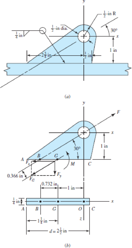
Brackets, such as the one shown, are used in mooring small watercraft. Failure of such brackets is usually caused by bearing pressure of the mooring clip against the side of the hole. Our purpose here is to get an idea of the static and dynamic margins of safety involved. We use a bracket 1/4 in thick made of hot-rolled 1018 steel, welded with an E6010 electrode. We then
assume wave action on the boat will create force F no greater than 1200 lbf.
(a) Determine the moment M of the force F about the centroid of the weld G. This moment produces a shear stress on the throat resisting bending action with a “tension” at A and “compression” at C.
(b) Find the force component Fy that produces a shear stress at the throat resisting a “tension” throughout the weld.
(c) Find the force component Fx that produces an in-line shear throughout the weld.
(d) Using Table 9–2, determine A, Iu, and I for the bracket.
(e) Find the shear stress τ1 at A due to Fy and M, the shear stress τ2 due to Fx, and combine to find τ.
(f) Find the factor of safety guarding against shear yielding in the weldment. Since the weld material is comprised of a mix of the electrode material and the base material, take the conservative approach of utilizing the strength of the weaker material.
(g) Find the factor of safety guarding against a static failure in the parent metal at the weld.
(h) Assuming the force F alternates between zero and 1200 lbf, find the factor of safety guarding against a fatigue failure in the weld metal using a Gerber failure criterion.
(a)
The moment
Answer to Problem 52P
The moment
Explanation of Solution
Write the expression for moment about
Here, force is
Conclusion:
Substitute
Thus, the moment
(b)
The force component
Answer to Problem 52P
The force component
Explanation of Solution
Write the expression for component of force
Here, force is
Conclusion:
Substitute
Thus, the force component
(c)
The force component
Answer to Problem 52P
The force component
Explanation of Solution
Write the expression for component of force
Here, force is
Conclusion:
Substitute
Thus, the force component
(d)
The area of throat, unit second moment of area and second area moment by using the Table
Answer to Problem 52P
The throat area is
The unit second moment of area is
The second area moment is
Explanation of Solution
Write the expression for throat area.
Here, thickness of weld is
Write the expression for unit second moment of area.
Here, thickness of weld is
Write the expression for second area moment about an axis
Here, thickness of weld is
Conclusion:
Substitute
Thus, the throat area is
Substitute
Thus, the unit second moment of area is
Substitute
Thus, second area moment is
(e)
The shear stress
The shear stress
The combined maximum shear stress
Answer to Problem 52P
The shear stress
The shear stress
The maximum shear stress is
Explanation of Solution
Write the expression for shear stress due to
Here, force in y-direction is
Write the expression for shear stress due to
Here, force in x-direction is
Write the expression for resultant shear stress at the throat plane.
Here, shear stress due to
Write the expression for secondary shear stress.
Here, Moment is
Write the expression for maximum shear stress.
Here, resultant shear stress at the throat plane is
Conclusion:
Substitute
Thus, the shear stress
Substitute
Thus, the shear stress
Substitute
Substitute
Substitute
Thus, the maximum shear stress is
(f)
The factor of safety guarding against shear yielding in the weldment.
Answer to Problem 52P
The factor of safety guarding against shear yielding in the weldment is
Explanation of Solution
Write the expression for factor of safety against guiding against shear yielding in weldment.
Here, yield stress is
Conclusion:
Refer to member of
Substitute
Thus, the factor of safety guarding against shear yielding in the weldment is
(g)
The factor of safety guarding against a static failure in the parent metal at the weld.
Answer to Problem 52P
The factor of safety guarding against a static failure in the parent metal at the weld is
Explanation of Solution
Write the expression for shear stress.
Here, force along x-direction is
Write the expression for normal stress along y-direction.
Here, force along x-direction is
Write the expression for von misses stress theory.
Here, normal stress is
Write the expression for factor of safety.
Here, yield stress is
Conclusion:
Substitute
Substitute
Substitute
Substitute
Thus, the factor of safety guarding against a static failure in the parent metal at the weld is
(h)
The factor of safety guarding against a fatigue failure in the weld metal using Gerber failure criterion.
Answer to Problem 52P
The factor of safety guarding against a fatigue failure in the weld metal using Gerber failure criterion is
Explanation of Solution
Write the expression for surface factor.
Here, ultimate tensile strength is
Write the expression for effective diameter.
Here, thickness of weld is
Write the expression for size factor.
Here, effective diameter is
Write the expression for equivalent strength.
Here, ultimate tensile strength is
Write the expression for endurance limit.
Here, surface factor is
Write the expression for axial shear stress.
Here, surface factor for shear is
Write the expression for factor of safety of Gerber criterion.
Here, maximum shear is
Conclusion:
Substitute
Substitute
Substitute
Substitute
Substitute
Substitute
Substitute
Thus, the factor of safety guarding against a fatigue failure in the weld metal using Gerber failure criterion is
Want to see more full solutions like this?
Chapter 9 Solutions
Shigley's Mechanical Engineering Design (McGraw-Hill Series in Mechanical Engineering)


- A polyethylene tube (length L) has a cap that when installed compresses a spring (with under-formed length L1) by an amount ?? = (L1 = L). Ignore deformations of the cap and base. Use the force at the base of the spring as the redundant. Use numerical properties given in the boxes. (a) What is the resulting Force-in the spring, Fk? (b) What is the resulting Force in the tube, Ftl (c) What is the filial length of the tube, Lf? (d) What temperature change ?T inside the tube will result in zero force in the springarrow_forward. A thin plate is composed of four CST elements, as shown inthe figure below. The plate is subjected to a uniform tensile traction sacting on the right edge and a concentrated force F at the center. Usethe following values: E = 105 GPa, ν = 0.3, t = 5 mm, L = 400 mm,H = 400 mm, s = 50 MPa, and F = 150 kN.(a) Compute all the nodal displacements.(b) For each element, compute the element stress components σxx, σyy,and τxy.(c) For each element, compute the element planar principal normal stressesσ1′ and σ2′.(d) For each element, compute the Von Mises and Tresca effective stresses. Please help solve using only FEM( Finite Element Method) and the values given, very urgent. Thank you.arrow_forwardTwo forces are applied to a flywheel 50 cm in diameter. Each force is 500 N. The shaft is fixed to the wall using three grade 5 steel bolts. The distance between the bolts and the axis of rotation is 10 cm. (a) What moment of resistance must develop the three bolts together Answer: 250 Nm (b) What is the resistance force F of each bolt? Answer: 833.3 N (c) What is the diameter of the bolts if their factor of safety is 10? Answer: 4.14mmarrow_forward
- A steam boiler, 1.2 meter in diameter, generates steam at a gauge pressure of 0.7 N/mm2. Assuming the efficiency of the riveted joints as 75%, find the thickness of the shell. Given that ultimate tensile stress = 385 MPa and factor of safety = 5arrow_forwardA stepped bar is fixed at end C. The bar has a cross sectional area of 1000 mm² in AB, and a 2000 mm² cross sectional area in BC. Young's Modulus of the bar's material is 200 GPa. A horizontal force of 100 kN is applied to cross section B. There is a gap b = 0.2mm between right end A and the rigid wall. If the bar is stretched to contact the rigid wall and is welded to it, determine the minimum horizontal force F that needs to be applied to end A. 300 mm 400 mm F A 0.2 mm B 100 KNarrow_forwardFind the equivalent stresses at Points 1 and 2 of the element with given geometry and loading conditions according to the Maximum shear stress hypothesis and the Maximum strain energy hypothesis. Shaft diameter: 20 mm, Shaft Length 120 mm, F1 = 750N, F2 = 3000N, Mb = 2400 N.mm. Steel if St37 and Safety coefficient is 2 If taken, will this stick work safely under these operating conditions? (Yield of given steel Strength 225 Mpa, Tensile strength 370 Mpa)arrow_forward
- A hard-drawn steel wire extension spring has a wire diameter of 4mm, an outside coil diameter of 28 mm, and initial tension of 1200 N is applied to the spring. The spring shows an extension of 85 mm. The approximate number of turns is 25. From the given information: Determine the physical parameters of the spring such as mean diameter, spring index, maximum shear stress, total number of turns, Wahl’s stress factor, free length of the spring, and pitch of the coilarrow_forwardA FEM analysis was used to analyse the safety of a mechanical component made by an average steel (E = 2 × 10⁵ MPa, v = 0.25, o, = 600 MPa). For a given loading scenario, the stress tensor E in a critical point is: Try -81 -186 Try Oyy 186 -37 -319 Calculate the von Mises equivalent stress oyM and indicate whether or not the stress condition is safe with respect to the related failure criterion. OVM = MPa Is the stress condition safe with respect to the related failure criterion: Oa. Yes Ob. Noarrow_forwardHow would I draw this free body diagram? I'm not entirely sure what is happening at A, is it a fixed wall support with rollers? So it would have Ax, Ay and Ma components? I am also unsure how to identify the equilibirum equations.arrow_forward
- There is a gap of δ = 0.05cm between the steel and copper bars seen in the figure. i) When the ambient temperature rises to 200oC, will there be a reaction force in the bearings? ii) If there is a reaction force, calculate the reaction forces RA and RB at points A and B. The cross-sectional area of both bars is equal and 5cm ^ 2. Materials;Modules of Elasticity: E Steel = 210 GPa E Copper = 120 GPa Expansion Coefficients: α Steel = 12.10-6 1 / 0C α Copper = 16.10-6 1 / 0Carrow_forwardYou choose to examine a bone, muscle, cartilage, tendon, ligament or even a single cell under horizontal load as a simple, movable, and pinned on one end model that buckles. Where y (x) = -K sin (2pix /L); Theta (x)=dy/dx=buckling angle; K=K (material, etc.) Find: a. buckling angle b. Theta (x) where y=0 c. y(x) where Theta =0; d. sketch y(x)arrow_forwardN for Newton, m for meter, mm for millimeter, N/(mm^2) for Stress, mm^2 or m^2 for Area, mm^4 for Moment of inertia and Nm for bending moment. Use brackets if the power is MINUS for Example: 0.00125 N =1.25*10^(-3)N. A member is formed by connecting two steel bars shown below. Assuming that the bars are prevented from buckling sideways, calculate the magnitude force "P" that will cause the total length of the member to decrease 0.56 mm the values of elastic modulus for steel is 215 MPa. Take H1 = 4 cm, H2 = 9 cm, top bar (R) is 3 x 3 cm and bottom bar (Q) is 5 x 5 cm. Also, determine the stress-induced in each section of the bar. Solution: i) Magnitude Force, P = ii) Stress-induced in the top bar = iii) Stress-induced in the bottom bar =arrow_forward
 Mechanics of Materials (MindTap Course List)Mechanical EngineeringISBN:9781337093347Author:Barry J. Goodno, James M. GerePublisher:Cengage Learning