Check Your Understanding In the circuit of Figure 15.11, L = 2.0 × 10 − 3 H, C =5 .0 × 10 − 4 F , and R = 40 Ω (a) What is the resonant frequency? (b) What Is the Impedance of the circuit at resonance? (c) If the voltage amplitude is 10 V, what is i ( t ) at resonance? (d) The frequency of the AC generator is now changed to 200 Hz. Calculate the phase difference between the current and the emf of the generator. The ac circuit shown in Figure 15.11, called an RLC series circuit, is a series combination of a resistor, capacitor, and inductor connected across an ac source. It produces an emf of Figure 15.11 (a) An RLC series circuit, (b) A comparison of the generator output voltage and the current the value of the phase difference ϕ depends on the values of R , C , and L.
Check Your Understanding In the circuit of Figure 15.11, L = 2.0 × 10 − 3 H, C =5 .0 × 10 − 4 F , and R = 40 Ω (a) What is the resonant frequency? (b) What Is the Impedance of the circuit at resonance? (c) If the voltage amplitude is 10 V, what is i ( t ) at resonance? (d) The frequency of the AC generator is now changed to 200 Hz. Calculate the phase difference between the current and the emf of the generator. The ac circuit shown in Figure 15.11, called an RLC series circuit, is a series combination of a resistor, capacitor, and inductor connected across an ac source. It produces an emf of Figure 15.11 (a) An RLC series circuit, (b) A comparison of the generator output voltage and the current the value of the phase difference ϕ depends on the values of R , C , and L.
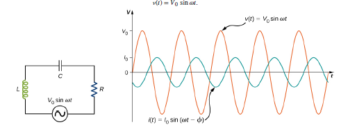
Check Your Understanding In the circuit of Figure 15.11,
L
=
2.0
×
10
−
3
H,
C
=5
.0
×
10
−
4
F
, and
R
=
40
Ω
(a) What is the resonant frequency? (b) What Is the Impedance of the circuit at resonance? (c) If the voltage amplitude is 10 V, what is
i
(
t
)
at resonance? (d) The frequency of the AC generator is now changed to 200 Hz. Calculate the phase difference between the current and the emf of the generator. The ac circuit shown in Figure 15.11, called an RLC series circuit, is a series combination of a resistor, capacitor, and inductor connected across an ac source. It produces an emf of Figure 15.11 (a) An RLC series circuit, (b) A comparison of the generator output voltage and the current the value of the phase difference
ϕ
depends on the values of R, C, and L.
Need a deep-dive on the concept behind this application? Look no further. Learn more about this topic, physics and related others by exploring similar questions and additional content below.


 Physics for Scientists and Engineers: Foundations...PhysicsISBN:9781133939146Author:Katz, Debora M.Publisher:Cengage Learning
 Physics for Scientists and Engineers, Technology ...PhysicsISBN:9781305116399Author:Raymond A. Serway, John W. JewettPublisher:Cengage Learning
 Glencoe Physics: Principles and Problems, Student...PhysicsISBN:9780078807213Author:Paul W. ZitzewitzPublisher:Glencoe/McGraw-Hill