
University Physics Volume 2
18th Edition
ISBN: 9781938168161
Author: OpenStax
Publisher: OpenStax
expand_more
expand_more
format_list_bulleted
Concept explainers
Textbook Question
thumb_up100%
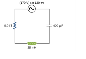
Chapter 15, Problem 29P
For the cucu3t shown below, what are (a) the total impedance and (b) the phase angle between the current and the emf? (C) Write, an expression for i(t).
Expert Solution & Answer
Want to see the full answer?
Check out a sample textbook solution
Students have asked these similar questions
The capacitance is 1.5 μFand the rms voltage is 25.0 V. What is the rms current
when the frequency is (a) 100 Hz and (b) 5000 Hz?
Paragraph
V
...
U A
BI
34
In the circuit given below,
ww wn
A) When the switch is in position 2 at t = 1 second, the current (Ic) and voltage
(Vc) in the capacitor depend on Find the mathematical expression.
B) What is the capacitor current (Ic) and voltage (Vc) at t = 2t seconds.
C) If the switch is set to position 2 at t = 2t ', it is necessary for the time
dependent change of voltage (Vc) across the capacitor. Find the mathematical
expression.
D) Draw the time-dependent waveform of the voltage determined for the
wwwm
conditions in items A, B and C.
w w
ic
4 mA
+
5 kΩ
R2
R
10 μFυc
1 kN
R3
3 kΩ
A capacitor, C'is connected across an emf given by:
v(t) = Vo sin(wt)
Write an expression for the current through the capacitor.
I(t) =
Chapter 15 Solutions
University Physics Volume 2
Ch. 15 - Check Your Understanding If a European ac voltage...Ch. 15 - Check Your Understanding Repeat Example 15.1 for...Ch. 15 - Check Your Understanding Find the voltages across...Ch. 15 - Check Your Understanding An ac voltmeter attached...Ch. 15 - Check Your Understanding Show that the tins...Ch. 15 - Check Your Understanding In the circuit of Figure...Ch. 15 - Check Your Understanding What happens to the...Ch. 15 - Check Your Understanding The resonant angular...Ch. 15 - Check Your Understanding A transformer steps the...Ch. 15 - What is the relationship between frequency and...
Ch. 15 - Explain why at high frequencies a capacitor acts...Ch. 15 - In an RLC series circuit, can the voltage measured...Ch. 15 - For what value of the phase angle between the...Ch. 15 - Discuss the differences between average power and...Ch. 15 - The average ac current delivered to a circuit is...Ch. 15 - Can the instantaneous power output of an ac source...Ch. 15 - The power rating of a resistor used in ac circuits...Ch. 15 - Why do transmission lines operate at very hig1...Ch. 15 - How can you distinguish the primary winding from...Ch. 15 - Battery packs in some electronic devices are...Ch. 15 - Will a transformer work if the input is a dc...Ch. 15 - Why are the primary and secondary coils of a...Ch. 15 - Write an expression for the output voltage of an...Ch. 15 - Calculate the reactance of a 5.0F capacitor at (a)...Ch. 15 - What is the capacitance of a capacitor whose...Ch. 15 - Calculate the reactance of a 5.0-mH inductor at...Ch. 15 - What is the self-inductance of a coil whose...Ch. 15 - At s1iat frequency is the reactance of a 20F...Ch. 15 - At 1000 Hz, the reactance of a 5.0-mH inductor is...Ch. 15 - A 50resistor is connected across the emf...Ch. 15 - A 25F capacitor is connected to an emf given by...Ch. 15 - A 100-mH inductor is connected across the emf of...Ch. 15 - What is the impedance of a series combination of a...Ch. 15 - A resistor and capacitor are connected in series...Ch. 15 - A resistor and inductor are connected in series...Ch. 15 - In an RLC series circuit, the voltage amplitude...Ch. 15 - An PLC series circuit with R=600 , L = 30 mH. and...Ch. 15 - For the cucu3t shown below, what are (a) the total...Ch. 15 - The emf of an ac source is given by v(t)=v0sint....Ch. 15 - Calculate the rms currents for an ac source is...Ch. 15 - A 40-mH inductor is connected to a 60-Hz AC source...Ch. 15 - For an RLC series circuit, the voltage amplitude...Ch. 15 - An ac source of voltage amplitude 10 V delivers...Ch. 15 - An RLC series circuit has an impedance of 60 and a...Ch. 15 - Calculate the resonant angular freqency of an RLC...Ch. 15 - The resonant frequency of RLC series circuits is...Ch. 15 - (a) What is the resonant frequency of an RLC...Ch. 15 - For an RLC series circuit, R=100 , L = 150 mH, and...Ch. 15 - An ac source of voltage amplitude 100 V and...Ch. 15 - (a) What is the resonant frequency of a resistor,...Ch. 15 - Suppose a coil has a self-inductance of 20.0 H and...Ch. 15 - An ac generator is connected to a device whose...Ch. 15 - A step-up transformer is designed so that the...Ch. 15 - A step-up transformer connected to a 100-V line U...Ch. 15 - An ac source of emf delivers 5.0 mW of power at an...Ch. 15 - A transformer is used to down 110 V from a wall...Ch. 15 - A transformer is used to supply a 12-V model train...Ch. 15 - The emf of an ac source is given by v(t)=V0sint,...Ch. 15 - A 700-pF capacitor is connected across an ac...Ch. 15 - A 20-mH inductor is connected across an AC source...Ch. 15 - A 30F capacitor is connected across a 60-Hz ac...Ch. 15 - A 7.0-mH induct is connected across a 60-Hz ac...Ch. 15 - What is the impedance of an RLC series circuit at...Ch. 15 - What is the resistance R in the circuit shown...Ch. 15 - An ac source of voltage amplitude 100 V and...Ch. 15 - In an RLC series circuit, R=200,L=1.0H ,...Ch. 15 - A power plant generator produces 100 A at 15 kV...Ch. 15 - Consider a power plant located 25 km outside a...Ch. 15 - Neon signs require 12-kV for their operation. A...Ch. 15 - The 335-kV ac electricity from a power...Ch. 15 - A 1.5k resistor and 30-mH inductor are connected...Ch. 15 - A 20 resistor, 50F capacitor, and 30-mH inductor...Ch. 15 - A 200- resistor, 150- F capacitor, and 23-H...Ch. 15 - Find the reactances of the following capacitors...Ch. 15 - An output impedance of an audio amplifier has an...Ch. 15 - Show that the SI unit for capacitive reactance is...Ch. 15 - A coil with a self-inductance of 16 mH and a...Ch. 15 - An RLC series circuit consists of a 50 resistor, a...Ch. 15 - An RLC series circuit consists of a 10 resistor,...Ch. 15 - Shown below are two circuits that act as crude...Ch. 15 - The two circuits shown below act as crude low-pass...
Additional Science Textbook Solutions
Find more solutions based on key concepts
6.73 •• You are asked to design spring bumpers for the walls of a parking garage. A freely rolling 1200-kg car ...
University Physics (14th Edition)
14.2 If an object on a horizontal, frictionless surface is attached to a spring, displaced, and then released, ...
University Physics with Modern Physics (14th Edition)
Using the definitions in Eqs. 1.1 and 1.4, and appropriate diagrams, show that the dot product and cross produc...
Introduction to Electrodynamics
What do we mean by the “universality” of physics and chemistry? Although we don’t know yet whether biology is s...
Life in the Universe (4th Edition)
Estimate the rate of entropy increase associated with your bodys normal metabolism.
Essential University Physics: Volume 1 (3rd Edition)
58. A kayaker needs to paddle north across a 100-m-wide harbor. The tide is going out, creating a tidal current...
College Physics: A Strategic Approach (4th Edition)
Knowledge Booster


Learn more about
Need a deep-dive on the concept behind this application? Look no further. Learn more about this topic, physics and related others by exploring similar questions and additional content below.Similar questions
- At s1iat frequency is the reactance of a 20F capacitor equal to that of a 10-mH inductor?arrow_forwardIn an oscillating RLC circuit, R = 7.0 L. = 10 mH. And C = 3.0 F. Initially, the capacitor has a charge of 8.0 C and the current is zero. Calculate the charge on the capacitor (a) five cycles later and (b) 50 cycles later.arrow_forwardThe current in the RL circuit shown below reaches half its maximum value in 0.5 ms after the switch S1 is thrown. Determine (a) the time constant of the circuit and (b) the resistance of the circuit if L = 200 mH. R Hints a. The time constant is TL = ms. b. The resistance R is Ω.arrow_forward
- The A.C. circuit consist of a resistor of 532 & inductor of 10 mitt connected on series with 50 nolt 50 H₂ supply. What capacitance should be connected in series with the circuit to obtain maximum current. Find the value of maximum current.arrow_forwardOcopper = 5.813x10' (2m)', Ho = 4tx10 H/m, ɛo = 8.85x10¹² F/m a) Find the high frequency model of a 500 2 resistor with 2.5 cm copper wire connections (radius = .2032 mm) and a stray capacitance Ca of 5 pF. Give an expression for the equivalent impedance. b) Sketch the impedance magnitude as a function of frequency. In your sketch also include the ideal behavior of the capacitor.arrow_forward. Consider the time @t = 2r. %3D a) What total energy, W, is stored in the circuit? b) Write the capacitive voltage divider expression for the voltage Vo, and solve for its value. 25 pF O Vo 5cosot V (A 100 pF 40 pF 80 pFarrow_forward
- A series RLC circuit consists of a 92.0 Ω resistor, a 0.180 H inductor, and a 39.0 μF capacitor. It is attached to a 120 V/60 Hz power line. What is the peak current I at this frequency?\ What is the phase angle phi? What is the average power loss?arrow_forwardIn the RLC circuit in the figure, R = 60Ω , L = 3 mH, C = 4 mF, and the source fem time variable has a maximum voltage of 120 V. What should be the angular frequency, to produce the greatest current in the resistor?arrow_forwardTo receive AM radio, you want an RLC circuit that can be made to resonate at any frequency between 500 and 1650 kHz. This is accomplished with a fixed 1.00 μH inductor connected to a variable capacitor. What would be the minimum capacitance, in nanofarads, that would be required? Cmin = Part (b) What would be the maximum capacitance, in nanofarads, that would be required? Cmax=arrow_forward
- A100 resistance is connected in series with The voltage voltage across the resistor is, 4H inductor. a V = (2.0 V) sin (10³ rad/s) (a) Find the expression of circuit current. (b) Find the inductive reactance.arrow_forwardPhase Angle. An LRC circuit has the following parameters: X₁ = 5N, Xc = 3N, and R= 20. Which of the following diagrams best represents the phasors of the current and source voltage of the LRC circuit at a certain point in time? V V V 45° A 90° с O A. Voltage leads current by 45° B. Current leads voltage by 45° C. Voltage leads current by 90° D. Current leads voltage by 90° 45° B 90° D Varrow_forwardThe series RLC circuit below has an input voltage of Vin(t) = 16 cos(5t) Volts. 2 H Vin .1 F a) Solve for the steady-state voltage across the capacitor, Vc(t). CdV instead of solving b) Find the steady-state current. (This can be done by using I = another ODE. If you want, you can check that these give the same answer.)arrow_forward
arrow_back_ios
SEE MORE QUESTIONS
arrow_forward_ios
Recommended textbooks for you

 Glencoe Physics: Principles and Problems, Student...PhysicsISBN:9780078807213Author:Paul W. ZitzewitzPublisher:Glencoe/McGraw-Hill
Glencoe Physics: Principles and Problems, Student...
Physics
ISBN:9780078807213
Author:Paul W. Zitzewitz
Publisher:Glencoe/McGraw-Hill