
Loose Leaf for Engineering Circuit Analysis Format: Loose-leaf
9th Edition
ISBN: 9781259989452
Author: Hayt
Publisher: Mcgraw Hill Publishers
expand_more
expand_more
format_list_bulleted
Concept explainers
Videos
Textbook Question
Chapter 4, Problem 16E
Using nodal analysis as appropriate, determine the current labeled i1 in the circuit of Fig. 4.46.
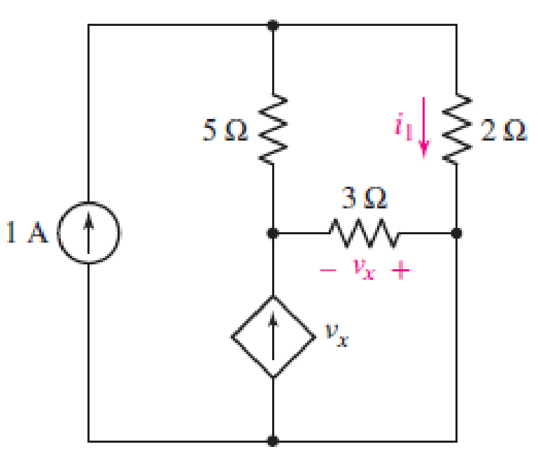
FIGURE 4.46
Expert Solution & Answer

Trending nowThis is a popular solution!

Students have asked these similar questions
Q4) By using Nodal analysis, find all voltages and currents.
4 k2
VA
1 k2
4 mA
Vc
14
10 V
2 k2
4 k2
LMH_chapter2-part2-homework. X
+
O File | C:/Users/DELL/Downloads/LMH_chapter2-part2-homework.pdf
(D Page view
A Read aloud
V Draw
E Highlight
4
of 15
Erase
HW3
4.27 Apply source transformation to find v, in the circuit
of Fig. 4.95.
10 Ω
12 2 b
20 Ω
a
+
50 V
40 Ω
8 A
40 V
11:05 PM
O Type here to search
A a O 4) E ENG
3/22/2021
近
c) Analyse the steady-state voltage vo(t) of the circuit in Figure Q4(b) if the input
voltage is given by:
v;(t) = 7.5 cos(2t - 122°) +2.2 cos(6t – 102°)
+1.3 cos(10t – 97°) + 0.91 cos(14t – 95°) + ... V
Show your answer for the first four terms of the output voltage, Vo(t).
Chapter 4 Solutions
Loose Leaf for Engineering Circuit Analysis Format: Loose-leaf
Ch. 4.1 - For the circuit of Fig. 4.3, determine the nodal...Ch. 4.1 - For the circuit of Fig. 4.5, compute the voltage...Ch. 4.1 - For the circuit of Fig. 4.8, determine the nodal...Ch. 4.2 - For the circuit of Fig. 4.11, compute the voltage...Ch. 4.3 - Determine i1 and i2 in the circuit in Fig. 4.19....Ch. 4.3 - Determine i1 and i2 in the circuit of Fig 4.21....Ch. 4.3 - Determine i1 in the circuit of Fig. 4.24 if the...Ch. 4.4 - Determine the current i1 in the circuit of Fig....Ch. 4.4 - Determine v3 in the circuit of Fig. 4.28. FIGURE...Ch. 4 - Solve the following systems of equations: (a) 2v2 ...
Ch. 4 - (a) Solve the following system of equations:...Ch. 4 - (a) Solve the following system of equations:...Ch. 4 - Correct (and verify by running) the following...Ch. 4 - In the circuit of Fig. 4.35, determine the current...Ch. 4 - Calculate the power dissipated in the 1 resistor...Ch. 4 - For the circuit in Fig. 4.37, determine the value...Ch. 4 - With the assistance of nodal analysis, determine...Ch. 4 - Prob. 9ECh. 4 - For the circuit of Fig. 4.40, determine the value...Ch. 4 - Use nodal analysis to find vP in the circuit shown...Ch. 4 - Prob. 12ECh. 4 - Prob. 13ECh. 4 - Determine a numerical value for each nodal voltage...Ch. 4 - Prob. 15ECh. 4 - Using nodal analysis as appropriate, determine the...Ch. 4 - Prob. 17ECh. 4 - Determine the nodal voltages as labeled in Fig....Ch. 4 - Prob. 19ECh. 4 - Prob. 20ECh. 4 - Employing supernode/nodal analysis techniques as...Ch. 4 - Prob. 22ECh. 4 - Prob. 23ECh. 4 - Prob. 24ECh. 4 - Repeat Exercise 23 for the case where the 12 V...Ch. 4 - Prob. 26ECh. 4 - Prob. 27ECh. 4 - Determine the value of k that will result in vx...Ch. 4 - Prob. 29ECh. 4 - Prob. 30ECh. 4 - Prob. 31ECh. 4 - Determine the currents flowing out of the positive...Ch. 4 - Obtain numerical values for the two mesh currents...Ch. 4 - Use mesh analysis as appropriate to determine the...Ch. 4 - Prob. 35ECh. 4 - Prob. 36ECh. 4 - Find the unknown voltage vx in the circuit in Fig....Ch. 4 - Prob. 38ECh. 4 - Prob. 39ECh. 4 - Determine the power dissipated in the 4 resistor...Ch. 4 - (a) Employ mesh analysis to determine the power...Ch. 4 - Define three clockwise mesh currents for the...Ch. 4 - Prob. 43ECh. 4 - Prob. 44ECh. 4 - Prob. 45ECh. 4 - Prob. 46ECh. 4 - Prob. 47ECh. 4 - Prob. 48ECh. 4 - Prob. 49ECh. 4 - Prob. 50ECh. 4 - Prob. 51ECh. 4 - Prob. 52ECh. 4 - For the circuit represented schematically in Fig....Ch. 4 - The circuit of Fig. 4.80 is modified such that the...Ch. 4 - The circuit of Fig. 4.81 contains three sources....Ch. 4 - Solve for the voltage vx as labeled in the circuit...Ch. 4 - Consider the five-source circuit of Fig. 4.83....Ch. 4 - Replace the dependent voltage source in the...Ch. 4 - After studying the circuit of Fig. 4.84, determine...Ch. 4 - Prob. 60ECh. 4 - Employ LTspice (or similar CAD tool) to verify the...Ch. 4 - Employ LTspice (or similar CAD tool) to verify the...Ch. 4 - Employ LTspice (or similar CAD tool) to verify the...Ch. 4 - Verify numerical values for each nodal voltage in...Ch. 4 - Prob. 65ECh. 4 - Prob. 66ECh. 4 - Prob. 67ECh. 4 - Prob. 68ECh. 4 - Prob. 69ECh. 4 - (a) Under what circumstances does the presence of...Ch. 4 - Referring to Fig. 4.88, (a) determine whether...Ch. 4 - Consider the LED circuit containing a red, green,...Ch. 4 - The LED circuit in Fig. 4.89 is used to mix colors...Ch. 4 - A light-sensing circuit is in Fig. 4.90, including...Ch. 4 - Use SPICE to analyze the circuit in Exercise 74 by...
Knowledge Booster


Learn more about
Need a deep-dive on the concept behind this application? Look no further. Learn more about this topic, electrical-engineering and related others by exploring similar questions and additional content below.Similar questions
- Homework: For the following circuit, find i, and. 4.1 4 k2 6 k2 20 mAarrow_forwardChapter Assessments I Series-Parallel Circuit Analysis A. Solve for the required values with complete solution and progressive simplified circuits. Box the final answer for the required values. 1. In Fig. 4.19, solve for Ry, Ir, l2, I4, and P R, = 75 0 R= 150 2 V,- 12 V R-330 0 R- 180 1 Figure 4.19 2. For each of the circuits shown in Fig. 4.20, a. find the equivalent resistance seen by the source, b. find the power developed by the source. 210 0 280 N 100 120Ω180Ω: १15 0 90 V/ 40 Ω 30 mA ( 200 2 25 0 (a) (b) Figure 4.20 3. For the network in Fig. 4.21 Note: E is also equivalent to the designation Vs or Vr for voltage source and Is is equivalent to lr for total current of the circuit being analyzed. a. Find currents Is, I2, and 16. b. Find voltages V1 and Vs. c. Find the power delivered to the 3 ka resistor.arrow_forward(Example 4.8) Determine all node voltages and branch currents assuming = 100. Assume Active +5 V 100 ΚΩ www +10 V 2 ΚΩarrow_forward
- 4.1 Find a Thévenin equivalent for the circuit shown with respect the 6 resistor. Use the Thévenin equivalent to find the current in the 6 2 resistor. If the 6 2 resistor were replaced with an 8 V source with positive terminal at the right, what would be the current in the source? 5 ohm w 40V 5 ohm 3 ohm 6 ohm ww 4 ohm 8 ohmarrow_forwardCopyright ©2012 The McGraw-Hill Companies. Permission required for reproduction or display. All rights reserved. www.nitropdf.com Engineering Circuit Analysis 8th Edition Chapter Four Exercise Solutions 58. One possible solution: Replace the independent current source of Fig. 4.28 with a dependent current source. 20 10Ω 100 V 3Ω 50 (a) Make the controlling quantity 8v1, i.e. depends on a nodal voltage. (b) Make the controlling quantity 8i, i.e. depends on a mesh current. Copyright ©2012 The McGraw-Hill Companies. Permission required for reproduction or display. All rights reserved. www.nitropdf.com Engineering Circuit Analysis 8th Edition Chapter Four Exercise Solutions 59. Referring to the circuit of Fig. 4.34, our two nodal equations arearrow_forwardUsing superposition technique, determine the value of Vx. Refer to figure 4.50I would also appreciate if you'll include another technique (nodal, mesh or source transformation) to compare the answer using superposition.arrow_forward
- D LMH_chapter2-part2-homework. X + O File | C:/Users/DELL/Downloads/LMH_chapter2-part2-homework.pdf of 15 D Page view A Read aloud V Draw E Highlight O Erase 15 HW14 4.74 For the bridge circuit shown in Fig. 4.140, find the load R, for maximum power transfer and the maximum power absorbed by the load. R1 R3 R1 R2 R4 9:48 PM O Type here to search ^ a O ) E ENG 3/25/2021arrow_forwardChapter Assessments I. Series-Parallel Circuit Analysis A. Solve for the required values with complete solution and progressive simplified circuits. Box the final answer for the required values. 1. In Fig. 4.19, solve for RT, IT, l2, l4, and P1 R,= 75 1 R= 150 1 V - 12 V R = 330 1 R= 180 Figure 4.19 2. For each of the circuits shown in Fig. 4.20, a. find the equivalent resistance seen by the source, b. find the power developed by the source. 210Ω 280 N 35 N 15 N 90 V( 10Ω 40 N 30 mA 200 Ω 120Ω180 Ωξ 25 N (a) (b) Figure 4.20arrow_forwardLMH_chapter2-part2-homework. X + O File | C:/Users/DELL/Downloads/LMH_chapter2-part2-homework.pdf 12 of 15 (D Page view A Read aloud V Draw E Highlight O Erase HW11 4.67 The variable resistor R in Fig. 4.133 is adjusted until it absorbs the maximum power from the circuit. (a) Calculate the value of R for maximum power. (b) Determine the maximum power absorbed by R. 80 Ω 20 Ω 40 V R ww 90 Ω 10Ω O Type here to search 10:04 PM ^ G O 4») E ENG 3/25/2021 近arrow_forward
- D LMH_chapter2-part2-homework. X + O File | C:/Users/DELL/Downloads/LMH_chapter2-part2-homework.pdf (D Page view A Read aloud V Draw E Highlight O Erase 10 of 15 HW9 Find the Norton equivalent at terminals a-b of the circuit in Fig. 4.119. 0.25v, 6Ω 2Ω a + 18 V 3 Ω 11:16 PM O Type here to search ENG 3/22/2021arrow_forwardII. A -to-Y Conversion A. Solve for the required values with complete solution and progressive simplified circuits. Box the final answer for the required values. 1. In Fig. 4.22, use delta-wye transformations to calculate both RT and IT with Vs 27 k, RB = 33 k, Rp = 39 k, RE 12 V and the following resistor values RA 47 k, and Rc = 100 k. Figure 4.22arrow_forwardD LMH_chapter2-part2-homework. X + O File | C:/Users/DELL/Downloads/LMH_chapter2-part2-homework.pdf D Page view A Read aloud V Draw E Highlight O Erase 11 of 15 HW10 *4.61 Obtain the Thevenin and Norton equivalent circuits A at terminals a-b of the circuit in Fig. 4.127. ML 2Ω o a 6Ω 12 V (+ I) 12 V 6 Q 2 2 12 V 11:16 PM O Type here to search ^ a D 4) E ENG 3/22/2021arrow_forward
arrow_back_ios
SEE MORE QUESTIONS
arrow_forward_ios
Recommended textbooks for you
 Introductory Circuit Analysis (13th Edition)Electrical EngineeringISBN:9780133923605Author:Robert L. BoylestadPublisher:PEARSON
 Delmar's Standard Textbook Of ElectricityElectrical EngineeringISBN:9781337900348Author:Stephen L. HermanPublisher:Cengage Learning
 Programmable Logic ControllersElectrical EngineeringISBN:9780073373843Author:Frank D. PetruzellaPublisher:McGraw-Hill Education
 Fundamentals of Electric CircuitsElectrical EngineeringISBN:9780078028229Author:Charles K Alexander, Matthew SadikuPublisher:McGraw-Hill Education
 Electric Circuits. (11th Edition)Electrical EngineeringISBN:9780134746968Author:James W. Nilsson, Susan RiedelPublisher:PEARSON
 Engineering ElectromagneticsElectrical EngineeringISBN:9780078028151Author:Hayt, William H. (william Hart), Jr, BUCK, John A.Publisher:Mcgraw-hill Education,
Introductory Circuit Analysis (13th Edition)
Electrical Engineering
ISBN:9780133923605
Author:Robert L. Boylestad
Publisher:PEARSON
Delmar's Standard Textbook Of Electricity
Electrical Engineering
ISBN:9781337900348
Author:Stephen L. Herman
Publisher:Cengage Learning
Programmable Logic Controllers
Electrical Engineering
ISBN:9780073373843
Author:Frank D. Petruzella
Publisher:McGraw-Hill Education
Fundamentals of Electric Circuits
Electrical Engineering
ISBN:9780078028229
Author:Charles K Alexander, Matthew Sadiku
Publisher:McGraw-Hill Education
Electric Circuits. (11th Edition)
Electrical Engineering
ISBN:9780134746968
Author:James W. Nilsson, Susan Riedel
Publisher:PEARSON
Engineering Electromagnetics
Electrical Engineering
ISBN:9780078028151
Author:Hayt, William H. (william Hart), Jr, BUCK, John A.
Publisher:Mcgraw-hill Education,
Norton's Theorem and Thevenin's Theorem - Electrical Circuit Analysis; Author: The Organic Chemistry Tutor;https://www.youtube.com/watch?v=-kkvqr1wSwA;License: Standard Youtube License