
Concept explainers
Videos
Find the value of
Answer to Problem 43E
The value of
Explanation of Solution
Calculation:
The circuit diagram is redrawn as shown in Figure 1,
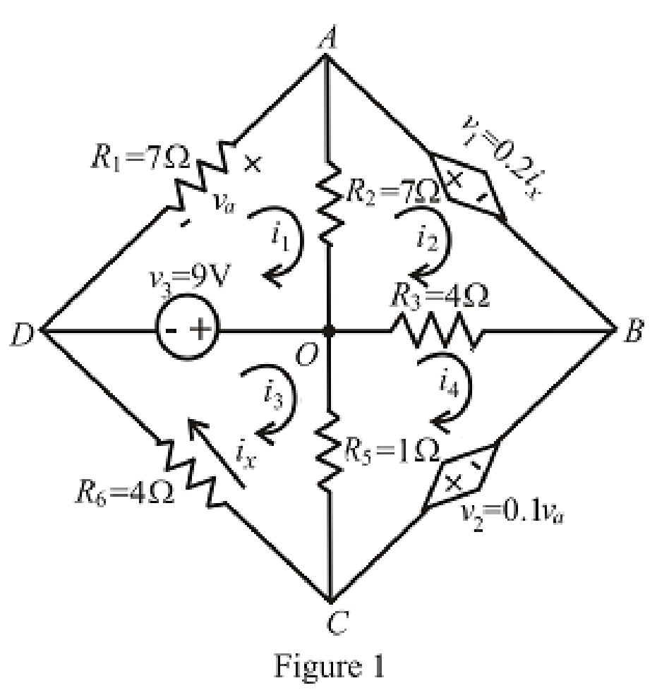
Refer to the redrawn Figure 1,
Apply KVL in the mesh
Here,
Apply KVL in the mesh
Here,
Apply KVL in the mesh
Here,
Apply KVL in the mesh
Here,
The expression for the voltage across
Here,
Refer to the redrawn Figure 1,
Substitute
Substitute
Substitute
Substitute
Rearrange the above equation for
Substitute
Substitute
Substitute
Substitute
Rearrange the equation (6), (10) and (11),
The equations so formed can be written in matrix form as,
Therefore, by Cramer’s rule,
The determinant of the coefficient matrix is as follows,
The 1st determinant is as follows,
The 2nd determinant is as follows,
The 3rd determinant is as follows,
Simplify for
Simplify for
Simplify for
The value of
Substitute
Conclusion:
Thus, the value of
Want to see more full solutions like this?
Chapter 4 Solutions
Loose Leaf for Engineering Circuit Analysis Format: Loose-leaf


- 51. Define three clockwise mesh currents for the circuit of Fig. 4.78 2, and employ the supermesh technique to obtain a value for v3. 42 5 V 1.8vy 3 V 20 FIGURE 4.78arrow_forwardFind t, in the circuit of Fig. 4.19 using source transformation. SV 10 ww 5A 30 70 ЗА Figure 4.19 For Practice Prob. 4.6.arrow_forward31. Use mesh analysis to find i, in the circuit shown in Fig. 4.61. 10 0 100 V FIGUREarrow_forward
- Obtain numerical values for the two mesh currents ij and iz in the circuit shown in Fig. 4.61. 32 5 V iz 12 V 14 2arrow_forwardFind the Norton equivalent circuit of the circuit in Fig. 4.45 at terminals a-h. 60 10 A 20 Figure 4.45 ww wwarrow_forward#7. Use Nodal analysis, Mesh Analysis, and Superposition to solve following problem: Determine v, in the circuit of Fig. 4.80]arrow_forward
- For the circuit in Fig. 4.3. find vo when i, = 15 and i, = 30 A. %3D is 2Ω 4 Ω: Figure 4.3 For Practice Prob. 4.1.arrow_forwardNumber 4.29 Use source transformation to find correctly Vo in the circuit of Fig. 4.97.arrow_forwardFor the circuit in Fig. 4.76, find the terminal voltage Vab using superposition. 4.8 3V ab 102 o a 4 V 2A Vab Figure 4.76 For Prob. 4.8.arrow_forward
- Employing the supermesh technique to best advantage, obtain numerical val- ues for each of the mesh currents identified in the circuit depicted in Fig. 4.71. 8 V 1A -2 A 10 ЗА 2 V 3 V FIGURE 4.71arrow_forward7. If the base resistor of Fig. 4.118 is increased to 910 kῼ, find the new Q -point and resultingvalues of ICQ and VCEQ.arrow_forwardQ5 Draw the output voltage waveform for each circuit in Fig. 4.30 with respect to the input. Show voltage levels. +I V +1 V 0- -I V +2 V Vutmery = 18 V -2 V (a) (b)arrow_forward
 Introductory Circuit Analysis (13th Edition)Electrical EngineeringISBN:9780133923605Author:Robert L. BoylestadPublisher:PEARSON
 Delmar's Standard Textbook Of ElectricityElectrical EngineeringISBN:9781337900348Author:Stephen L. HermanPublisher:Cengage Learning
 Programmable Logic ControllersElectrical EngineeringISBN:9780073373843Author:Frank D. PetruzellaPublisher:McGraw-Hill Education
 Fundamentals of Electric CircuitsElectrical EngineeringISBN:9780078028229Author:Charles K Alexander, Matthew SadikuPublisher:McGraw-Hill Education
 Electric Circuits. (11th Edition)Electrical EngineeringISBN:9780134746968Author:James W. Nilsson, Susan RiedelPublisher:PEARSON
 Engineering ElectromagneticsElectrical EngineeringISBN:9780078028151Author:Hayt, William H. (william Hart), Jr, BUCK, John A.Publisher:Mcgraw-hill Education,